|
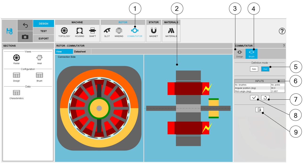
| COMMUTATOR – Brush - Overview |
| 1 |
Selection of the ROTOR subset: COMMUTATOR panel (Click on the
icon COMMUTATOR) |
| 2 |
Visualization of the motor radial and axial views to visualize
the commutator topology including brushes |
| 3 |
Commutator design tab to stablish global parameters, both
geometrical and electrical |
| 4 |
Brush design tab to introduce brush related parameters |
| 5 |
Choice of the commutator-brush definition mode. Two options are
available:
- Auto: Brushes dimensions and angular position are
automatically calculated by FluxMotor to get the best fit
with the defined winding (see below)
- User: Brushes dimensions and angular position are defined by
the user
|
| 6 |
Commutator-brush input data to be defined (only available in user
mode) |
| 7 |
Button to restore default input values |
| 8 |
Button to apply inputs. Pressing the enter key twice applies
inputs too. |
| 9 |
Icon to export shaft data into *.txt or *.xlsx files. |