Description of sub areas
Introduction
In each of three main areas (Machine, Rotor and Stator), there are sub areas, which allows defining a sub section of the machine such as shaft, housing, slots, winding, magnets, polarization, materials.
Sub area design view
 |
|
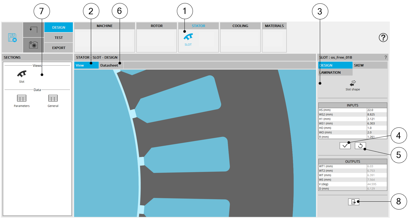
| Motor Factory – Design sub areaExample - Sub area of Stator dedicated to the design of slot topology – Main view | |
| 1 | Icon to access the sub area (Slot area in this example) |
| 2 | The default screen allows displaying the main view which illustrates the purpose of the study |
| 3 | Inputs are always displayed on the right part of the screen |
| 4 | Button to apply inputs |
| 5 | Button to restore default values |
| 6 | Each sub area has its own design report. It is visible under the tab “Datasheet” |
| 7 | Shortcuts allow reaching main section of the current design report |
| 8 | Icon to export data into *.txt or *.xls files. |
The next table described the tab “Datasheet”.
Sub area Datasheet
 |
|
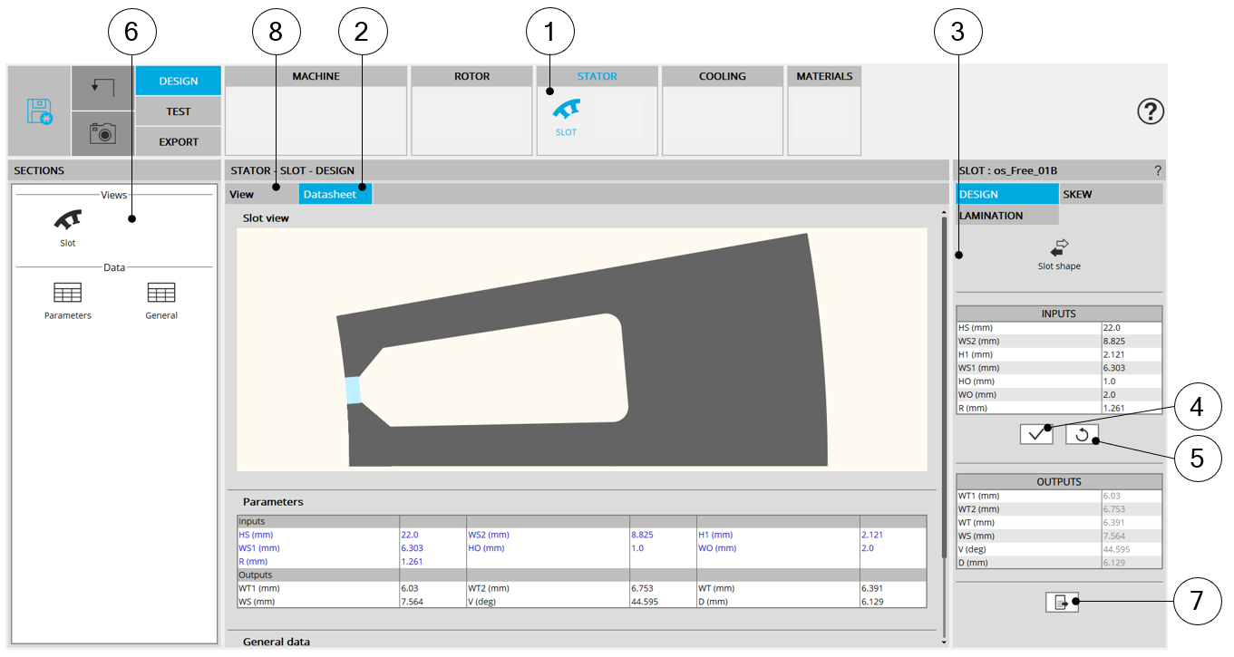
| Motor Factory – Design sub areaExample - Sub area dedicated to the design of slot topology – Datasheet view | |
| 1 | Icon to access the sub area (Slot area in this example) |
| 2 | Each sub area has its own design report. It is visible under the tab “Datasheet”Note: Input data are written in blue, Output data are written in black |
| 3 | Inputs are always displayed on the right part of the screen |
| 4 | Button to apply inputs |
| 5 | Button to restore default values |
| 6 | Shortcuts allow reaching main section of the current design report |
| 7 | Icon to export data in text files - Please see below illustration |
| 8 | The default screen which illustrates the purpose of the study |