The reference vector specifies the reference direction for a waveguide
port.
The reference vector is indicated by a white line connecting the edge of a waveguide with
the centre of the waveguide port and shows the direction of m, where m
corresponds to:
the number of half-wavelengths across the width of the waveguide (rectangular
waveguides).
the number of radial variations (circular waveguides).
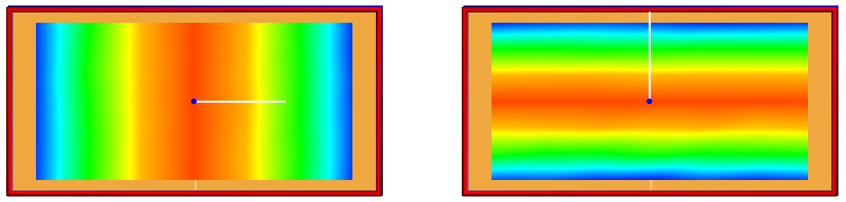
Figure 1. On the left, the reference vector is defined in the direction of the
waveguide width. To the right, the reference vector is defined in the direction
of the waveguide height.
For a rectangular waveguide, defining the reference vector in one direction, the dominant
mode at a frequency might be TE10. Rotating the reference vector with
90° and solving the same problem, the dominant mode will be
indicated as TE01.
For a circular waveguide there is no ambiguity with regards to which direction is for
m or n.
Note: Information given for the modes in the .out file corresponds to the specified direction of the reference
vector.
If the reference vectors differ between ports, it results in a phase mismatch between the
S21 and S11.
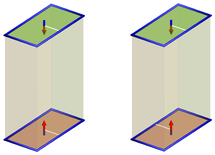
Figure 2. Two waveguide ports with equal reference directions (on the left) and two
waveguide ports with opposite reference directions (to the right). For both
these cases, the magnitude for S11 and S21 are identical.
For the case where the reference directions differs, the phase for S21 differ by
180° from S11.