Adding a PCB Source
Apply impressed line currents in the model to represent a printed circuit board (PCB). The impressed line currents are equivalent to the current values calculated for the traces and vias of a PCB.
-
On the Source/Load tab, in the
Equivalent Sources group, click the
 PCB Source
icon.
PCB Source
icon.
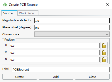
Figure 1. The Create PCB source dialog.A preview of the PCB outline is displayed in green in the 3D view.