Defining a Workplane on the Quadcopter
Define a workplane on the top face of the quadcopter.
-
On the Construct tab, in the Define group, click the
 Add Workplane icon.
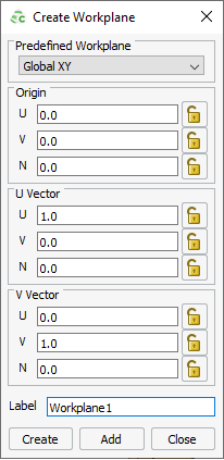
Figure 1. The Create Workplane dialog. -
Press Ctrl+Shift while moving the mouse
cursor over the top face centre of the quadcopter.
Note: The circles with a black outline indicate special snapping points. The red outline indicates the position of the mouse cursor.
Use snapping points to snap the workplane to an object. Although only special snapping points are indicated, you can snap to any point in the 3D view.
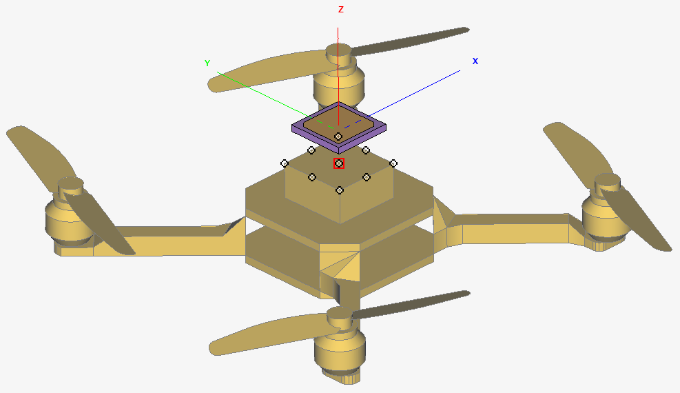
Figure 2. Special snapping points are indicated by circles with a black outline. -
Click Create to create the workplane and to close the
dialog.
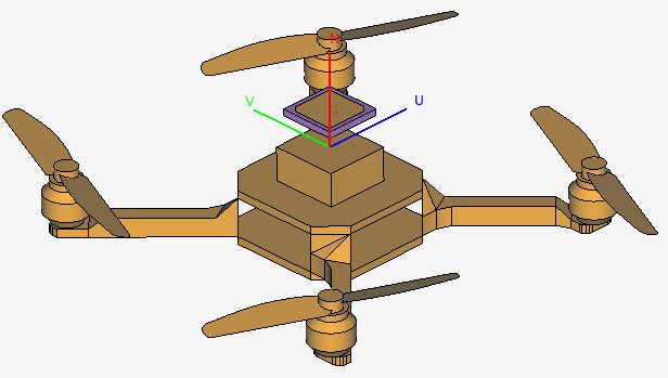
Figure 3. Workplane has snapped to the top centre of the quadcopter.