Tutorial: Designing a Circuit with Spice Components
Learn how to design a circuit with a Band Pass Filter using Spice components.
Files for This Tutorial
aop.lib; BandPassFilter.scm, filter.scm; OP_NON.cir*
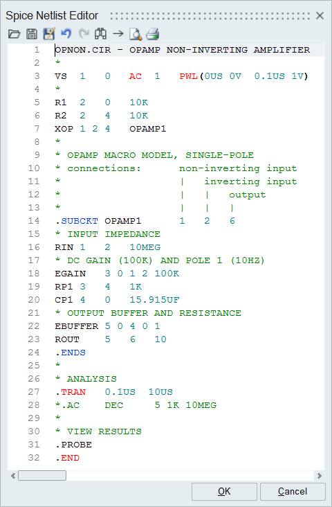
OPNON.CIR - OPAMP NON-INVERTING AMPLIFIER
*
VS      1       0      AC      1      PWL(0US 0V  0.1US 1V)
*
R1      2       0      10K
R2      2       4      10K
XOP     1 2     4      OPAMP1
*
* OPAMP MACRO MODEL, SINGLE-POLE
* connections:      non-inverting input
*                   |   inverting input
*                   |   |   output
*                   |   |   |
.SUBCKT OPAMP1      1   2   6
* INPUT IMPEDANCE
RIN      1      2      10MEG
* DC GAIN (100K) AND POLE 1 (10HZ)
EGAIN    3 0    1 2    100K
RP1      3      4      1K
CP1      4      0      15.915UF
* OUTPUT BUFFER AND RESISTANCE
EBUFFER  5 0    4 0    1
ROUT     5      6      10
.ENDS
*
* ANALYSIS
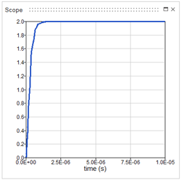
.TRAN    0.1US  10US
*.AC     DEC     5 1K 10MEG
*
* VIEW RESULTS
.PROBE
.END
Overview of the Spice Circuit Model
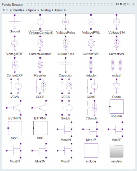
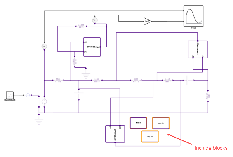
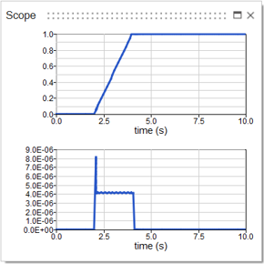
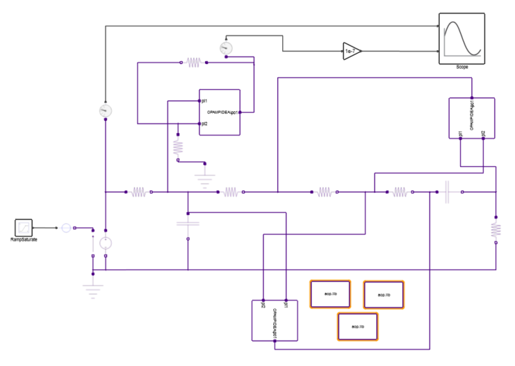
In this tutorial, you will construct a circuit out of blocks from the HyperSpice palette.
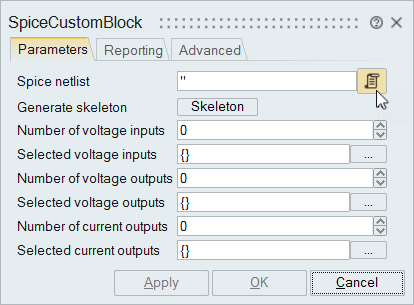
Create a Model with a Spice Custom Block
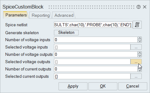
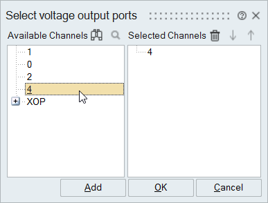
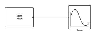
Add a SpiceCustomblock and Scope block to you model.
Create a Spice Model from a Modelica Model
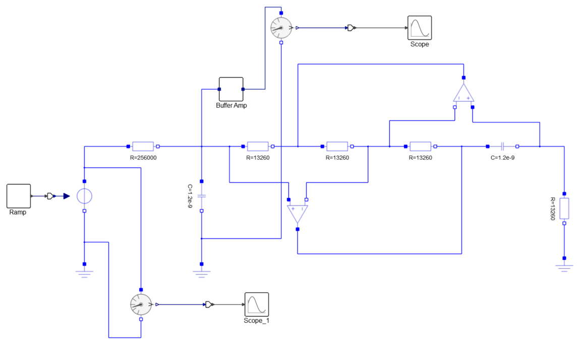
Create a circuit with components from the HyperSpice palette. Base your model on the Modelica example that is provided.
Complete the Spice Model
Add an xinst block to your model and reference the block through a Spice.lib file.
