Drawing the Outer Walls
Define the outer walls of the building.
-
Verify that the X/Y window is active, or activate it by
clicking in it.
The X/Y symbol in the top-left of the window is red when the window is active.
-
Create outdoor walls in the X/Y window using one of the following
workflows:
- On the Objects menu, click .
- On the Objects toolbar, click
the
 Add polygonal objects with orthogonal walls and a
ceiling icon.
Add polygonal objects with orthogonal walls and a
ceiling icon.
- Click twice at (-10, 6) to specify the first corner the polygon.
-
Click at the following coordinates to specify the corners of the polygon, for
example:
- (-5, 6)
- (-5, 0)
- (7, 0)
- (7, -5)
- (-10, -5)
-
Right-click at (-10, 6) to close the polygon.
Figure 1. View of the model in the XY plane (top view) showing the outer walls. 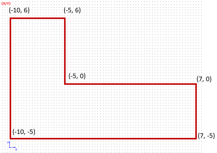
Note: All outer surfaces (including the floor and ceiling) of the building are created. The material is brick with a thickness of 10 cm. -
Exit the draw mode using one of the following workflows:
- On the Objects menu, click .
- On the Objects toolbar, click
the
 Select Object icon.
 - Press F10 to use the keyboard shortcut.