Connected Pins
This rule checks whether specific components are connected.
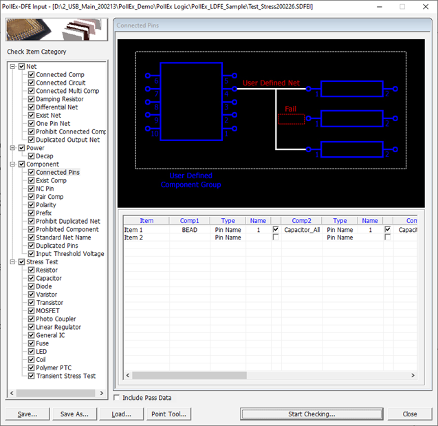
- Comp1: Select 1st target passive component group.
- Type: Define
PIN selection method. (Pin Name/Signal Name)
- Pin Name: Target Pin is selected by its pin number.
- Signal Name: Target Pin is selected by its pin name.
- Name: Enter PIN or Signal name.
- Comp2: Select 2nd target passive component group.
- Type: Define
PIN selection method. (Pin Name/Signal Name)
- Pin Name: Target Pin is selected by its pin number.
- Signal Name: Target Pin is selected by its pin name.
- Name: Enter PIN or Signal name.
- Comp3: Select 3rd target passive component group.
- Type: Define
PIN selection method. (Pin Name/Signal Name)
- Pin Name: Target Pin is selected by its pin number.
- Signal Name: Target Pin is selected by its pin name.
- Name: Enter PIN or Signal name.
- Net: Select net group to which passive components should be connected.
- Except Net: Define net group to be excluded.
- Standard Net: Enter a string to choose specific net from all nets.
- Check whether Comp1 exist or not: If you select, DFE will check Comp1 for the existence of selected parts in the drawing.
- Composite
Power Net: Upon selecting this menu, DFE use composited power net instead of
single power net. Double-click the item field, the Composite Power
Net dialog opens.
Figure 2. 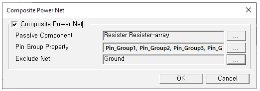
- Passive Component: The DFE make composite net for which are connected through this passive component.
- Pin Group Property: In the case of a passive component of 3pin or more, pin mapping information is required for composite. Set the Property Name with pin mapping information.
- Exclude Net: Nets which should not be merged into composite net.