Router JIG Rule Setup
Set the rules for creating Router JIG.
-
Vacuum Hole: Set the standard for generating vacuum holes for passing the end
mil of the router machine and for sucking dust.
Figure 1. 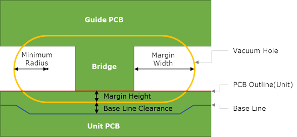
- Min Radius: Set the radius of the vacuum hole.
- Margin Width: Enter a margin width between the edge of the bridge and the vacuum hole.
- Margin Height: Enter a margin height between the bridge’s cutting edge (unit PCB outline) and the vacuum hole.
- Base Line Clearance: The base line is generated by avoiding the vacuum hole as much as the entered value.
-
Base Line: Set standard base line.
When the SMD process is completed, the array panel PCB should be mounted on the router-machine JIG. The engraved machining area should be designed to avoid interference with components.
Figure 2. 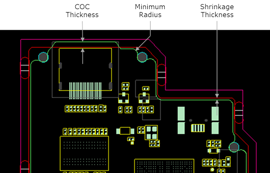
-
Size: Enter the conditions to determine the size of the router-machine
JIG.
Figure 3. 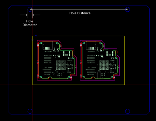
- Hole Distance: Enter the distance of the JIG fixing hole.
- Hole Diameter: Enter the diameter of the JIG fixing hole.
-
PBA: An engraving process to match the panel PCB shape is performed to mount
the array panel PCB that completes the SMD process. The handle space should be
designed to detach the PCB from the router-machine JIG by an operator.
Figure 4. 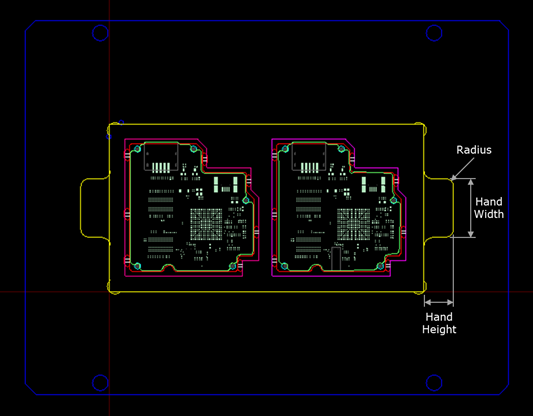
- Hand Width: Enter the width of the handle space.
- Hand Height: Enter the height of the handle space.
- Radius: Enter the radius of the handle space.
-
Bottom: Enter the standard for making the unevenness on the bottom of
router-machine JIG.
Figure 5. 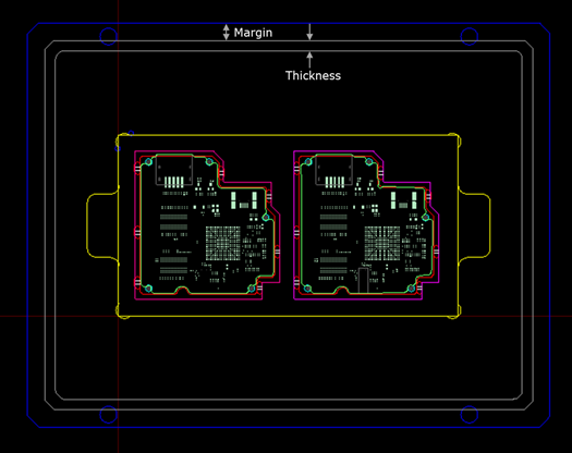
- Margin: Enter the margin from the outside of the router-machine JIG.
- Thickness: Enter the uneven width of the opposite side of the router-machine JIG.