PCB Outline and Bridge Recognition
-
Select Gerber Layer: Select a Gerber Layer to select an outline and bridge
object of panel board.
The selected Gerber layer displays on the screen.
Figure 1. 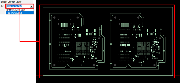
-
Select Top Component: Select the CAD data layer that corresponds to the top
surface during the screen print process.
The components placed on the bottom surface are engraved in the base line area to avoid interference with the Block JIG. Therefore, if the top side is selected, the component area placed on the bottom is referred to when creating the base line, and vice versa.
Figure 2. 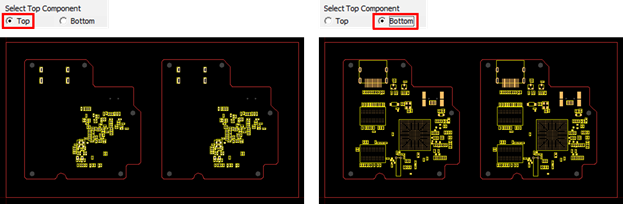
-
Recognize Bridge area for generating the vacuum hole is automatically
recognized from the Gerber data.
When the unit PCB outline and the panel PCB outline are parallel, a pair line at the right angle is regarded as a bridge region. With the recognition of the bridge area, the vacuum hole is generated with a red line.
Figure 3. 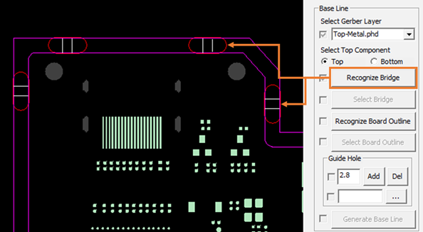
- Select Bridge: When the bridge is not recognized automatically through Recognize Bridge, the bridge can be manually set by selecting two lines.
-
Recognize Board Outline: Distinguishes and recognizes each closed outline
considering the connection status of the outline. The closed outlines display in
different colors when you click Recognize Board
Outline.
Figure 4. 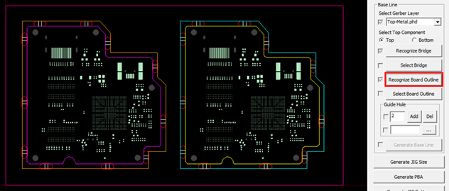
-
Select Board Outline: Board outline is created based on the unit PCB outline
when creating the base line. Select the outlines corresponding to the unit PCB
among the outlines separated through the Recognize Board Outline.
Figure 5. 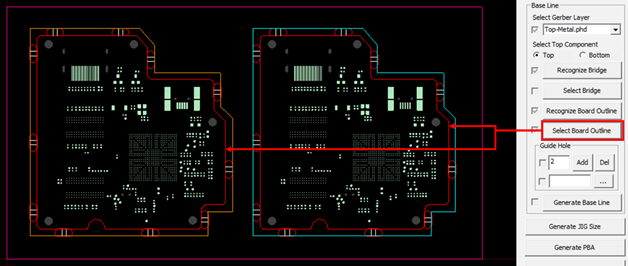
-
Guide Hole: When creating a base line, it should be generated avoiding the
guide hole. Set guide hole in one of the following ways:
Figure 6. 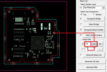
Method Steps Manual - Enter the diameter of the guide hole.
- Click Add. Click the location directly on the window to generate the guide hole.
- Click Del. The selected guide hole is deleted.
- Use component group
From Component Group - Click
 open file to select the
pre-generated component DB (*.txt)
file.
open file to select the
pre-generated component DB (*.txt)
file.
-
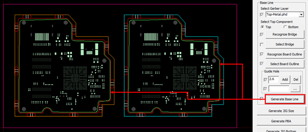
Generate Base Line: Click Generate Base Line.
The base line is generated in green.
Figure 7.