Explore Tool Functions
From the menu bar of Metal Mask Manager, click Tools.
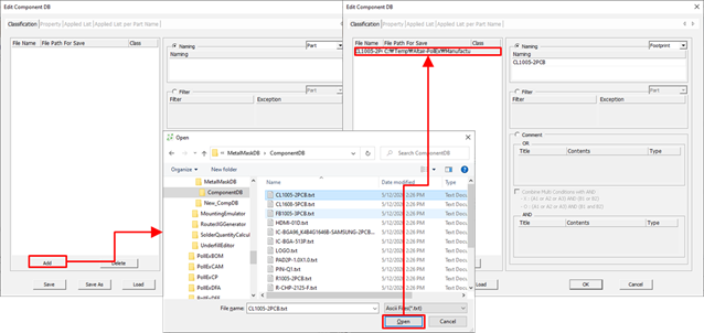
Component DB
From the menu bar of Metal Mask Manager, click .
The Edit Component DB dialog opens.
Metal Mask Manager has the function to save standard metal mask shape into database file. So, if components are having same padstacks and they are classified into different type, you can register different standard metal masks for them.
Metal Mask Manager’s database file, *.mmdb can detect component through component classification file, *.txt. Because of this reason, you need to prepare well-equipped component classification file data structure.
Classification
In the Edit Component DB, the Classification tab contains the following sections:
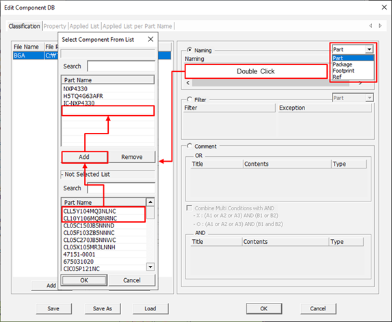
- Component Name Selection Filter: Using this filter, you can set the filter type to be used to select components among part name, package name, footprint name, or reference name.
- Add: Upon double-clicking naming field, tool shows the Select Component From List dialog. From the list in Not Selected List, select components and add components into upper list as selected component list.
- Remove: After selecting components in selected component list, click Remove to remove item from the list. Removed item will be moved to Not Selected List.
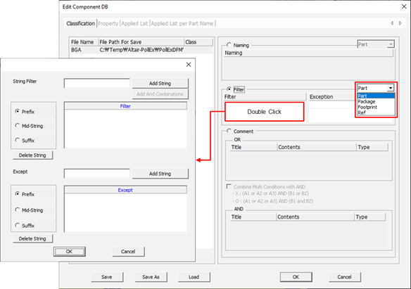
- Component Filter: Users can set the filter type to be used to select components among part name, package name, footprint name, device name and reference name.
- String Filter: Add string to be included into component classification database.
- Affix Filter: For string added in the String Filter, select its usage type
among prefix string, middle string, or suffix string in component name.
- Prefix: Component name should be started with given string.
- Mid-String: Given strings should be in component name.
- Suffix: Component name should be ended with given string.
- Add String: With conditions in String Filter and Affix Filter, make a filter and add it into list.
- Add And Combination: For set filtering conditions, add conditions combination for String Filter and Affix Filter, with And combination. For example, if users want to select components which name starts with SMD character string and end with IC character string, use the following ways. After input SMD in string filter, select Prefix and press Add String button. Then, input IC in string filter, select Suffix for affix filter and press Add And Combination button.
- Except String Filter: For the filer conditions generated by String Filter ~ Add And Combination sections, input character string which users want to exclude.
- Affix Filter: For character string in Except String Filter, select its usage
among Prefix, Mid-String or Suffix.
- Prefix: Component name should be started with given string.
- Mid-String: Given strings should be in component name.
- Suffix: Component name should be ended with given string.
- Add String: Add filer conditions into list for filtering condition, set in Except String Filter and Affix Filter.
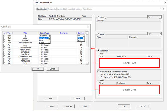
- v: Column for checking component properties will be used.
- Type: Show component property type.
- Title: Show property title.
- Select Type: Select component property setting method.
- List Select: Setting method by selecting properties list defined in design.
- Filter: Setting method by using string filter to set components which have matched properties.
- Range: Setting method by specifying the range when the property value is numeric.
- Contents: Upon double-clicking the contents column,
depending on selection type in Select Type column, tool will launch Comment
Select, String Filter, or Range Setting window.
- List Select: You can set design’s component properties in Select
Comment window. Using method is same as Naming.
Figure 5. 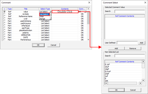
- Filter: Method to set component group with components’ property
value. Using method is same as Filter.
Figure 6. 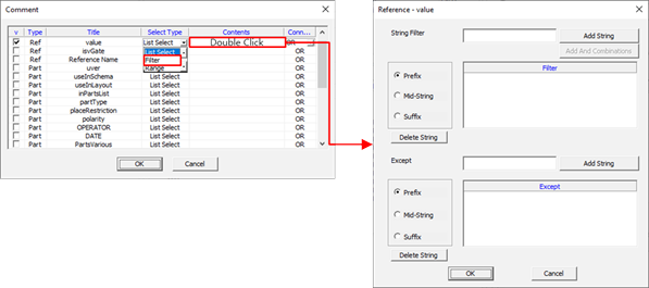
- Range: You can specify the parts within the numerical range when the
property value is numeric.
Figure 7. 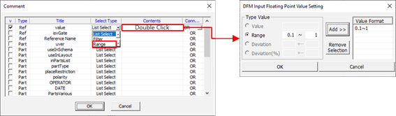
- List Select: You can set design’s component properties in Select
Comment window. Using method is same as Naming.
- Connected: Field to set condition is OR or AND combination.
Figure 8. 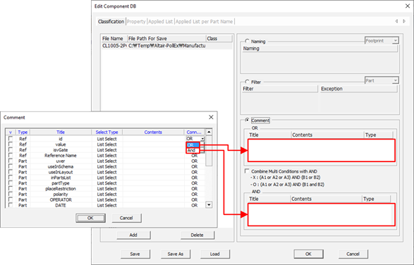
- OR: In case of set property is matching with one of component properties.
- AND: In case of set property is matching with component properties in OR field and with component properties in AND field. For example, OR(A1, A2, A3), OR(B1, B2) means (A1 ∪ A2 ∪ A3) ∩ (B1 ∪ B2).
Property
- Title Display Window: You can check component property (Comment) title.
- Contents: Upon selecting each property title, you can see components property values.
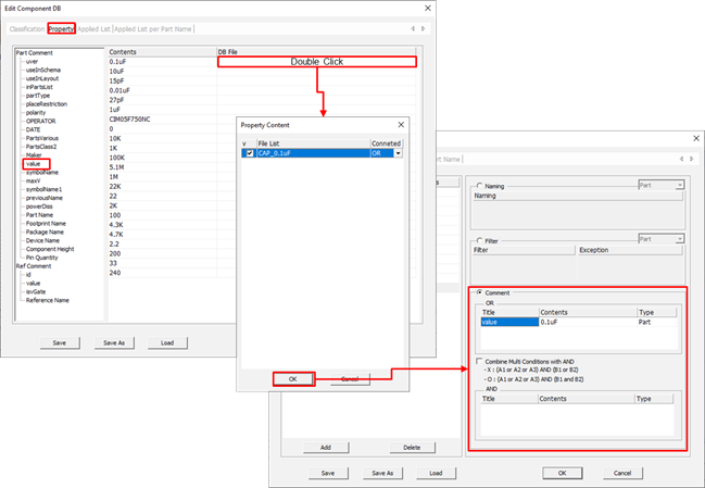
- DB File: You can verify component DB file having selected component property value (Content). Upon double-clicking certain line, Property Content window will be shown.
- Property Content Window: You can check component DB list created in classification. Using component DB file, you can register property values (Contents).
Standard of Mask Design
- Package Metal Mask DB: Shows the path of current opened metal mask database file, *.mmdb.
- Open: Open metal mask database file, *.mmdb.
Figure 10. 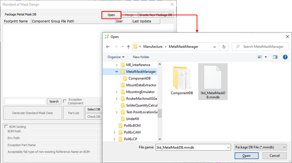
- Merge: Use this menu to merge another metal mask database into current Database.
- Create New Package DB: Create new metal mask database, *.mmdb.
- Lists of metal mask database
- The parts marked in blue are set with the standard Metal Mask set differently from the CAD data.
- Search: Search a component.
- Exception Component: Upon setting exceptional component database, you can exclude them from generating standard metal mask database.
- Generate Standard Mask Data: Generate standard metal mask using design’s mask data.
- Part List: Linking with part viewer in PollEx PCB,
you can review part information.
Figure 11. 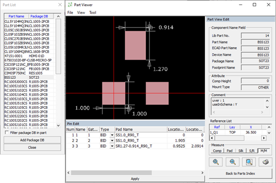
- Select DB: Multiple component DB could be used for making metal mask database. To select component DB, use this menu.
- Check DB: Check whether used components are in metal mask database,
*.mmdb and whether those components pads’ standard
metal masks are existing or not. After checking, you can see the result in
table-driven format.
- Part: Component’s part name.
- Package: Component’s package name.
- Pad Stack: Padstack’s name which is not in standard metal mask.
- DB: Shows whether component database is registered or not in metal mask database, *.mmdb.
- Standard Mask: Shows whether standard metal mask is registered or not in metal mask database, *.mmdb.
- Pins: Pin number not registered in standard metal mask shape.
- Edit: You can edit selected component in component list.
- Export To: Export component list to MS/Excel.
- Generate Metal Mask Shape from ECAD Design: Among components in
design, users can generate and register standard metal mask shape
and component DB for components which are not registered in metal
mask database, *.mmdb.
- Component DB Path: Specify component DB file path.
Figure 12. 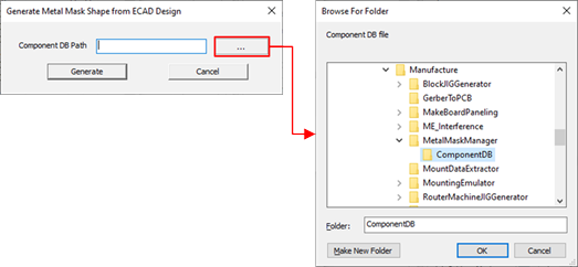
- Component DB Path: Specify component DB file path.
- New: To register new component DB and components’ standard metal mask, tool launch new metal mask DB setting window (Refer to section Metal Mask Registration Method).
- Edit: Change components’ standard metal mask which are selected in the Lists of metal mask database. After pressing this menu button, tool launch new metal mask DB setting window (Refer to section Metal Mask Registration Method).
- Delete: Remove selected component group from the Lists of metal mask database. Selected component DB will not be removed in file system.
- Change Component DB Directory: Change component DB file path registered in metal mask DB.
- BOM Setting: For used components in design, if they are not in BOM, tool
will not make standard metal mask shape. To do this purpose, use BOM Setting
option.
- BOM Path: Select MS Excel formatted BOM file.
- Env Path: Set MS Excel file reading environment file, *.ebi. Making EBI file is only available in PollEx BOM.
- Exception Part Name: Set exceptional component DB for validation check.
- Acceptable fail type of non-existing Reference Name: Set allowable component DB in validation checking if they are not in BOM.
- Contraction (%): Set contraction ratio when creating the Metal Mask through
the Generate Standard Mask Data menu.
- Layer: Specify the layer to reflect the contraction.
- Direction: Select one of 9 points for contraction rate.
- Horizontal(X): Set the horizontal axis contraction rate.
- Vertical(Y): Set the vertical axis contraction rate.
Metal Mask Registration Method
Click New in the Standard of Mask Design dialog. The Metal Mask DB Setting dialog opens.
- Footprint Name: Denotes footprint name. Same name as defined in the Component DB File.
- Component DB File: Set DB file, *.txt which you want to register. Upon reading component DB file,
*.txt, padstack list
matching used components in design with component DB will appear.
- Pad Stack Name: Padstack name.
- Metal Mask: You can check user-defined standard metal mask.
- Width: Padstack’s width.
- Length: Padstack’s length.
- Import Metal Mask Shape from Other Package: Import the Standard Metal Mask shape registered in Padstack with the same name from other parts.
- Create Metal Mask for Undefined Sharp from CAD Data: In case of padstacks which
are not having standard metal mask shape, you can automatically register
standard metal mask shape with design’s metal masks.
Figure 13. 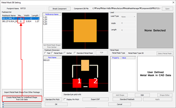
- Pad Stack Dimension: You can review padstack’s dimension.
Figure 14. 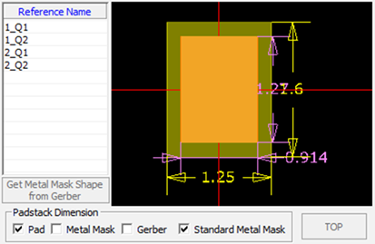
- Pad: Measure the size of pads.
- Metal Mask: Measure the size of metal mask used in the design.
- Gerber: Measure the size of Gerber file’s metal mask. To use this function, refer to metal_mask_manager_explore_tool_functions_r.htm#reference_bsf_sbc_dsb to calibrate Gerber and design file.
- Standard Metal Mask: Measure the size of standard metal mask.
- Lead: Input lead’s shape property for selected pad.
- Lead Type: Specify the type of lead.
- Width: Specify the width of lead.
- Length: Specify the length of lead.
- Metal Mask: After selecting shape and size, you can register metal mask
shape.
- Edit: After selecting padstack, click Edit to edit it.
- Select Metal Mask: Upon selecting this menu, the Metal Mask
Type dialog opens.
Figure 15. 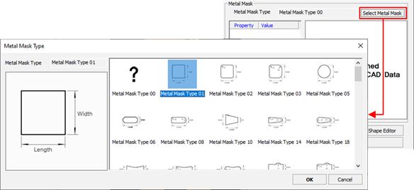
- Tool provides selected metal mask shape’s size and offset (X/Y)
value.
Figure 16. 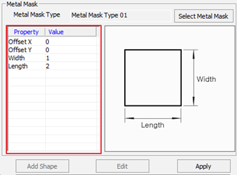
- Shape Editor: Complex shapes that do not exist in the Metal Mask Type can be drawn directly through the Shape Editor.
- Standard Padstack: Using the pads’ name and size (width/height), you can
check whether design’s mask data are following the standard rule or
not.
Figure 17. 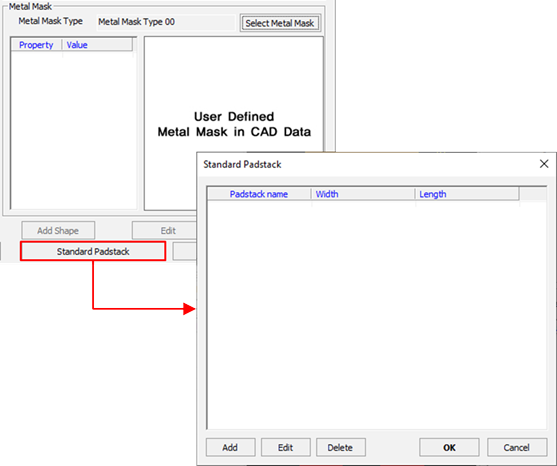
- Add: Register standard pads. After clicking Add,
specify padstack name, pad’s width, and length.
Figure 18. 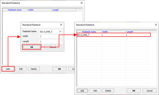
- In case of editing properties, click Edit.
Figure 19. 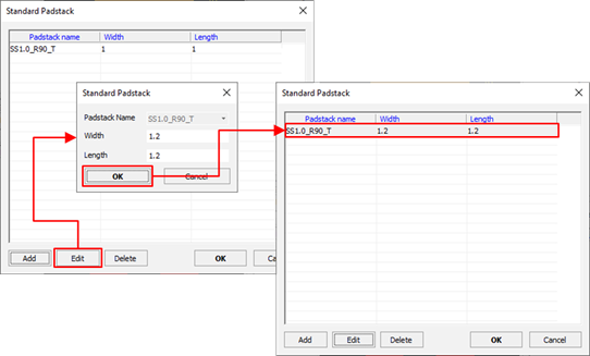
- Apply: Using this menu, you can check the metal mask shapes in package
DB.
Figure 20. 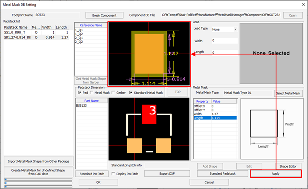
- OK: Upon clicking OK, tool
saves current properties and launch Package Data Information window. At this
window, you can add comments of changing history. To manage changing history,
click from the menu bar.
Figure 21. 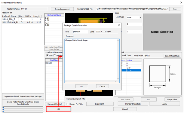
Validation Check
From the menu bar of Metal Mask Manager, click .
The Validation Check dialog opens.
Clearance Check Input
The Validation Check dialog contains the following sections.
Among design’s metal mask, metal mask in metal mask DB, *.mmdb and Gerber file’s metal mask, Metal Mask Manager can compare and find the difference.
- Select Gerber files for compare with Metal Mask: Set the layer top or bottom
metal mask for Gerber file’s data. Before launching Metal Mask Manager, you should import Gerber file in
PollEx PCB.
- Select for TOP Metal Mask: Select Gerber file for top metal mask layer.
- Select for Bottom Metal Mask: Select Gerber file for bottom metal mask layer.
- BOM Setting
- BOM: Select MS Excel formatted BOM file path.
- Env: To automatically read MS Excel formatted file, tool needs environment file, *.ebi. Making EBI file is only available in PollEx BOM.
- Exception Part: Set component DB file which will be excluded in validation checking.
- Acceptable fail type of non-existing Reference Name: Set component DB which will be allowable in validation check even if those components are not in BOM.
- Select Check Type: Set checking composition.
- Gerber vs Standard of Mask Design: Use this option to compare Gerber’s metal mask and metal mask in metal mask DB, *.mmdb.
- Gerber vs CAD: Use this option to compare Gerber’s metal mask and design’s metal mask.
- CAD vs Standard of Mask Design: Use this option to compare design’s metal mask and metal mask in metal mask DB, *.mmdb.
- Property
- Tolerance: Set allowable error tolerance in validation checking.
Validation Check Result
Refer to metal_mask_manager_explore_tool_functions_r.htm#reference_i2s_xzb_dsb.
Clearance Check
From the menu bar of Metal Mask Manager, click .
The Clearance Check dialog opens.
This function is to check the clearance between Metal Mask, Solder Mask, and Via generated by Generate Standard Mask Design of Metal Mask Manager.
Clearance Check Input
- Clearance between Standard of Masks in same Component: Checking clearance between Metal Mask shapes corresponding to the pins in the same component.
- Clearance between Standard of Mask and other Component’s Standard Mask:
Checking clearance between Metal Mask Shape and other components.
- Except checking for overlapped pads: Option to exclude Metal Mask of overlapped pins when designed overlapped pads.
- Clearance between Standard of Mask and Board Figure Metal Mask (CAD): Checking clearance between generated Metal Mask and Board Figure Metal Mask on CAD data.
- Clearance between Standard of Mask and Solder Mask: Checking clearance between generated Metal Mask and Solder Mask on CAD data.
- Clearance between Standard of Mask and Via: Checking clearance between generated Metal Mask and Via.
Clearance Check Result
When completed the Clearance Check, the results are displayed in list at the bottom of Metal Mask Manager window. You can save the result as an Excel file by clicking Export Excel.
Gerber Export
Metal Mask Manager can export metal mask file into Gerber using standard metal mask DB, *.mmdb.
From the menu bar of Metal Mask Manager, click . The Gerber Export Option dialog opens.
The Gerber Export Option dialog contains the following options:
- Board Outline Width: Specify the width of Board Outline on Gerber export.
- Generate Metal Mask Gerber from Cad Data: Export Metal Mask shape of CAD data to Gerber.
- Generate Metal Mask Gerber from Standard of Mask Design: Export to Gerber
using Metal Mask Shape registered in the Standard of Mask Design DB.
- Include Board Figure Metal Mask from Cad Data: Include Metal Mask designed as Board Figure properties on CAD data.
- Include Component Figure Metal Mask from Cad Data where not existing Standard of Mask Design: Include the Component Figure Metal Mask shape on CAD data, not registered in Standard of Mask Design DB.
- Include Metal Mask from Cad Data for undefined Standard of Mask Design: Include Metal Mask shape on CAD data for the pad not registered in the Standard of Mask Design DB.
- Design File Folder: Generate Gerber file in the path where CAD data exists.
- User Defined Folder: Generate Gerber file in the user defined path.
Standard Padstack Size
This is the feature to check size between design’s pad and standard metal mask data pad.
From the menu bar of Metal Mask Manager, click . The Standard Padstack Size dialog opens. Using the user-definable tolerance value, you can check between two different pads.
Standard Pin Pitch
This is the feature to check pin pitches between stand pin pitch in metal mask DB, *.mmdb and design’s pin pitch.
From the menu bar of Metal Mask Manager, click . The Standard Pin Pitch dialog opens.
Using the user-definable tolerance value, you can check between two different pins pitches.
Regarding Standard Pin Pitch Check Result, refer to metal_mask_manager_define_properties_r.htm#reference_tjt_jnh_dsb.
Measure
From the menu bar of Metal Mask Manager, click .
- Object: Measure by the radius, diameter, horizontal/vertical size.
- Object to Object: Measure the distance between objects.
- Edge: Measure based on the edge of the selected objects.
- Center: Measure based on the center of the selected objects.
- Minimum Distance: Measure the minimum distance of the selected objects.
- Delta X: Measure the distance by fixing the horizontal axis.
- Delta Y: Measure the distance by fixing the vertical axis.
- Use Same Type: Apply the same measures to the Second Type as selected from the Fist Type.
- Point to Point: Measure the distance between user selected points.
- Dimension Display
- Keep: Keep the results of measurement until the window is closed.
- Text Scale: Change the text scale to display either smaller or larger.
Compare with BOM
Using design and BOM, you can check whether Gerber’s metal mask data constructed or not.
Before checking it, reading Gerber file will reduce time. From the menu bar of Metal Mask Manager, click . The Compare with BOM dialog opens.
The Compare with BOM dialog contains the following sections:
- Select Metal Mask layer from Gerber files.
- Select Top Metal Mask Layer: Specify top metal mask Gerber layer.
- Select Bottom Metal Mask Layer: Specify bottom metal mask Gerber layer.
- Select Option
- Exception Part Name: Specify component DB to set components which will be excluded from checking.
- Acceptable fail type of non-existing Reference Name on BOM: Specify component DB to set components which will be allowable, even if they are not in BOM.
- Exception
- None: No exception.
- IC Visual Mark: Option to exclude IC Visual Mark from checking.
- Standard Metal Mask DB: Option to exclude metal masks in design using metal mask database file, *.mmdb.
- Line Width on Gerber: Exclude Gerber data line having specified width.
- BOM Setting
- BOM Path: Specify the BOM file path.
- Env Path: Specify the file path of BOM reading environment, *.ebi.
Comparison Result
- Comparison Result: Shows checking result. Error types will be metal mask,
BOM and part.
- METAL MASK: In case of components exist in design and BOM, but metal mask data are missing in design.
- BOM: In case of components in design having matching mask in Gerber, but components are not in BOM.
- PART: In case of components in design do not have matching metal mask in Gerber.
- Export to: Export checking result to MS Excel file.