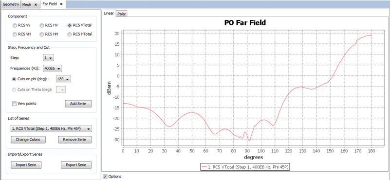
Example 2
In this example, the bistatic RCS of a flare is calculated using a frequency sweep from 0.4 GHz to 0.6 GHz (400 MHz to 600 MHz).
Step 1
Create a new project using Step 1 to Step 5 discussed in Example 1.
Step 2
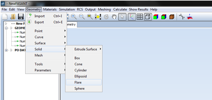
Click on Geometry → Solid → Flare.
Step 3
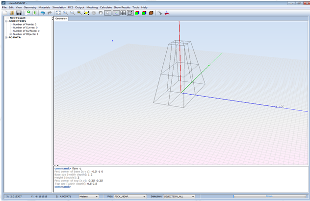
Enter the following parameters to define the flare in the command line as shown in the next Figure:
· First corner of base [x y z] -0.5 -1 0
· Base size [width depth] 1 2
· Height 2
· First corner of top [x y] -0.25 -0.25
· Top size [width depth] 0.5 0.5
Step 4
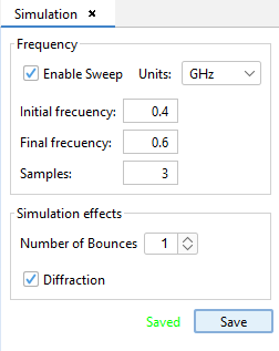
Select Simulation → Parameters. Select 1 bounce (simple reflection), and define the diffraction and a frequency sweep from 0.4E9 Hz to 0.6E9 Hz (400 MHz to 600 MHz) as shown in the next Figure, and left-click on Save button.
Step 5
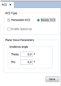
Select RCS → Parameters. Define the parameters as shown in the following Figure, and left-click the Save button.
Step 6
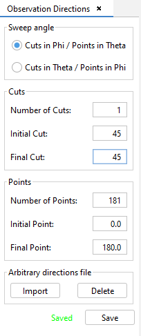
Select Output and left-click on Observation directions. Define the parameters as shown in the next Figure, and left-click the Save button.
Step 7
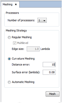
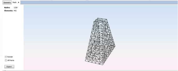
Select Meshing → Create Mesh. Define the parameters as shown in the next Figure, and left-click the Mesh button.
Step 8
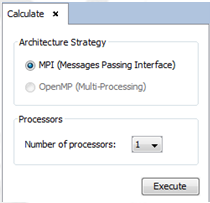
Then select Calculate → Execute and enter the number of processors to be used in this simulation.
Step 9
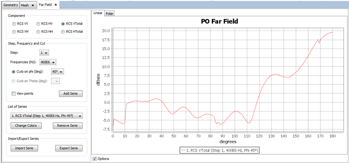
Select Show Results → Far Field → View Cuts.
Step 10
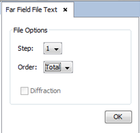
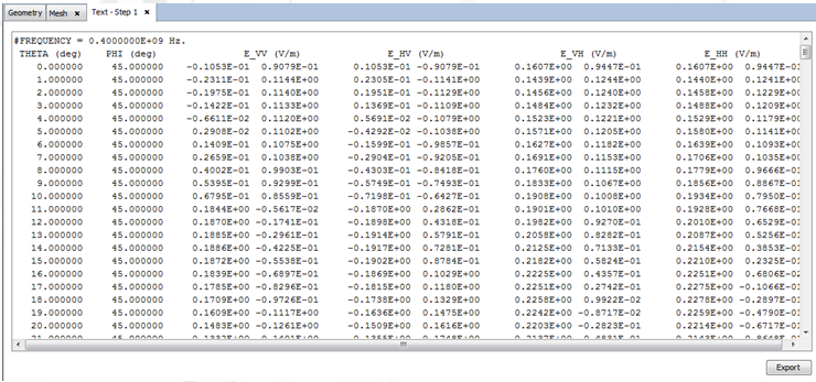
Select Show Results → Far Field → View Text Files.
Step 11
Select Materials → Add to add a new material to the simulation in the new panel shown at the right side of the window.
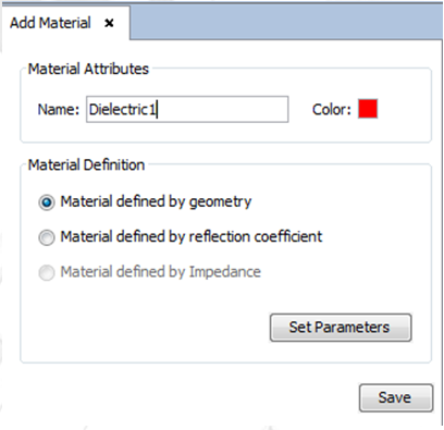
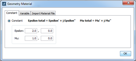
Then select the “Material defined by Geometry” option and also left-click the “Set Parameters” button to define the material properties as shown in the next Figure. Press Save.
Step 12
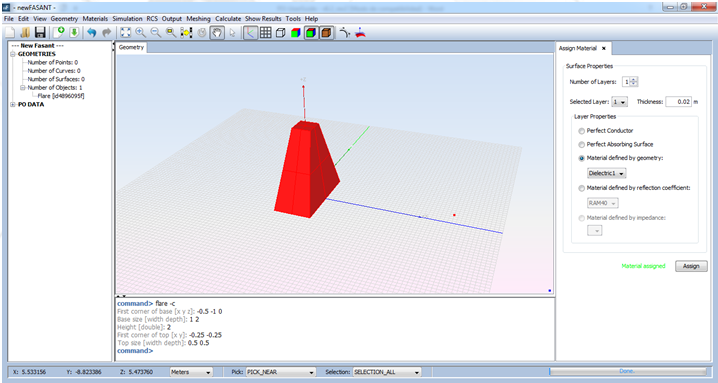
Select Material → Assign to assign the new material properties to the geometry. Select the object and left-click the “Assign” button as shown in the next Figure.
Step13
Re-mesh the geometry and run the simulation again. Then open the new RCS results shown in the next Figure.
