Specify Fans
Identify the components that represent fans in the model.
Fans are modeled like wheels, a boundary condition is prescribed and a rotational speed is applied.
Select the parts that form the fan, such as blades and hub. The center and axis of rotation are automatically computed. However, the rotational speed needs to be provided. Virtual Wind Tunnel for ultraFluidX supports three approaches for fans: Frozen, MRF, and Overset. In Frozen or MRF models, the fan does not rotate in the simulation. An MRF volume improves modeling of the swirling flow created by a fan. To simulate a truly rotating fan, use an Overset mesh model. With an Overset volume, the fan and mesh inside is rotated to accurately represent the flow and rotating fan.
-
From the ultraFluidX ribbon,
Setup group, click
the Identify Parts tool.

Figure 1. -
From the secondary tool set, click the Create Fans
tool.

Figure 2.The Fan dialog opens. -
Create a volume around the fan by completing one of the following:
Choice Selection Import a previously created volume - Select Select.
- Browse, select, and import the previously created volume.
Create a cylinder volume - Select Cylinder.A tightly wrapped cylinder volume is automatically created around the fan.Tip: You can adjust the size of the cylinder by selecting the diameter or height labels in the modeling window and entering a new value in the microdialog.
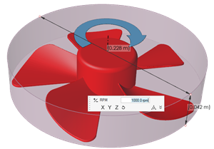
Figure 3.
Create a Solid Revolution volume - Select Solid Revolution.A CAD geometry is automatically created around the fan.Tip: You can adjust the offset size by entering a new value for Offset. If the Offset is too large, a warning will be given.
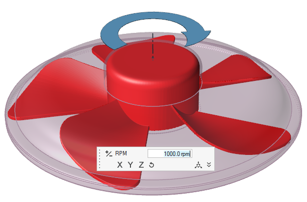
Figure 4.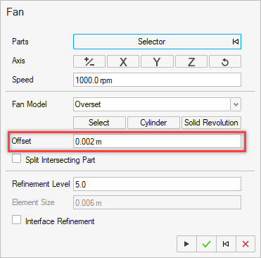
Figure 5.
- Optional:
To check for and split intersecting parts, enable the Split
Intersecting Part checkbox.
A color coded legend displays which indicates any intersecting, interior, and exterior parts. When the fan is created, the intersecting parts are split.
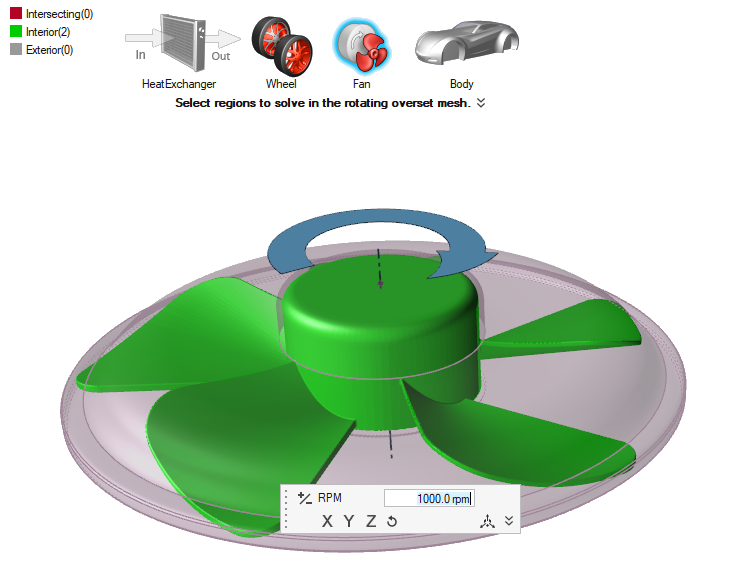
Figure 6. -
Complete one of the following:
- Select
 to confirm your selections and continue
specifying fans.
to confirm your selections and continue
specifying fans. - Select
 to
confirm your selections and exit the dialog and tool.
to
confirm your selections and exit the dialog and tool. - Select
 to clear your
selections and start over.
to clear your
selections and start over. - Select
 to exit the
tool without confirming your selections.
to exit the
tool without confirming your selections.
- Select