What's New
View new features for Virtual Wind Tunnel for ultraFluidX 2022.3.
Altair Virtual Wind Tunnel for ultraFluidX 2022.3 Release Notes
Highlights
The Virtual Wind Tunnel 2022.3 release includes the following highlights:
- Guide panel to setup fans.
- Solid of revolution for fan Overset mesh region.
- Automated coarse mesh precursor simulations.
- Import unit selector for STL/NAS files.
- Multiple measurements on the same surface part.
- Mesh Controls dialog for advanced mesh settings.
New Features
- Guide Panels
- A guide panel interface walks you through the setup process for a fan in
a unified interface. This replaces the multiple-select icons and
separate guide bar based workflows for Overset and MRF zones. All
options are now presented in the same dialog and you can mix and match
relevant features. The guide panel will configure automatically based on
the choices you make. Figure 1 shows a Frozen fan model and Figure 2 shows a fan with an Overset mesh model.
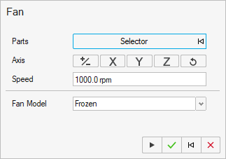
Figure 1.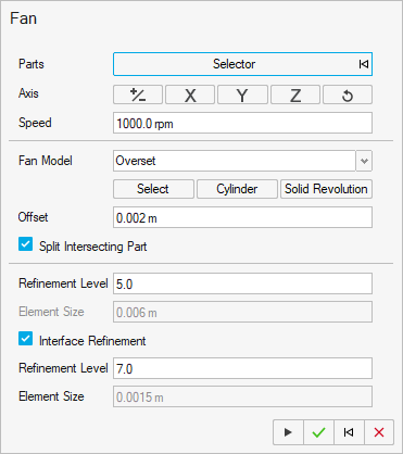
Figure 2. - Solid of Revolution
- An automatic solid of revolution can now be computed for rotating parts,
such as fans and wheels. The input geometry for this feature can be a
Parasolid part or a discrete STL/NAS part. This feature is exposed via
Python API and is also available as an option in the guide panel for
fans. An optional offset parameter can be used to further refine the
solid volume.
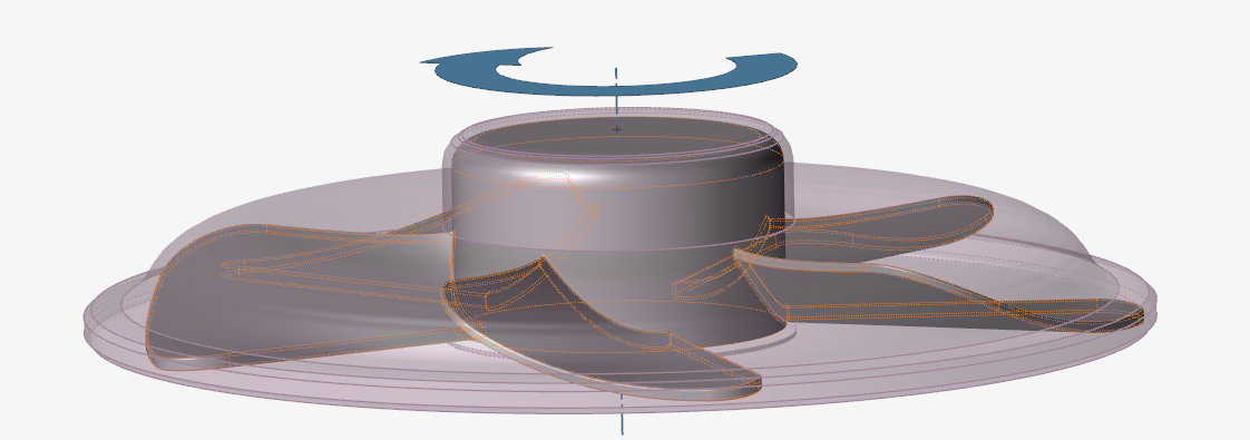
Figure 3. - Automatic Precursor Simulation
- The startup phase of large simulations can be accelerated by using
results from a coarse precursor simulation. This can be done
automatically from the Run dialog where you can
specify the factor of coarseness. For advanced users, a standalone
script
precursorRunis provided that will generate the .xml input files for the coarse and fine simulations.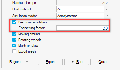
Figure 4. - Mesh Control Parameters and Dialog
- A dedicated Mesh Controls dialog has been created
where you can access global mesh settings and advanced meshing
parameters. This includes new settings that have been added, such as:
- Triangle splitting for surface outputs
- Triangle plinth visualization
- Refinement level mesh transition layers
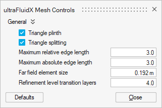
Figure 5. - Output Control for Overset Mesh Files
- Overset meshes can generate a large amount of mesh data and controls to
restrict it have been added:
- Restrict *geo output files every time step in the Output Controls dialog.
- A new mesh_displacement variable can be enabled in the relevant outputs.
Enhancements
- Import Units Dialog
- When importing discrete models without units, such as STL or NAS files,
you will be prompted to specify the Length unit. This enables you to
visualize the imported part in relation to the existing part in the
modeling window.
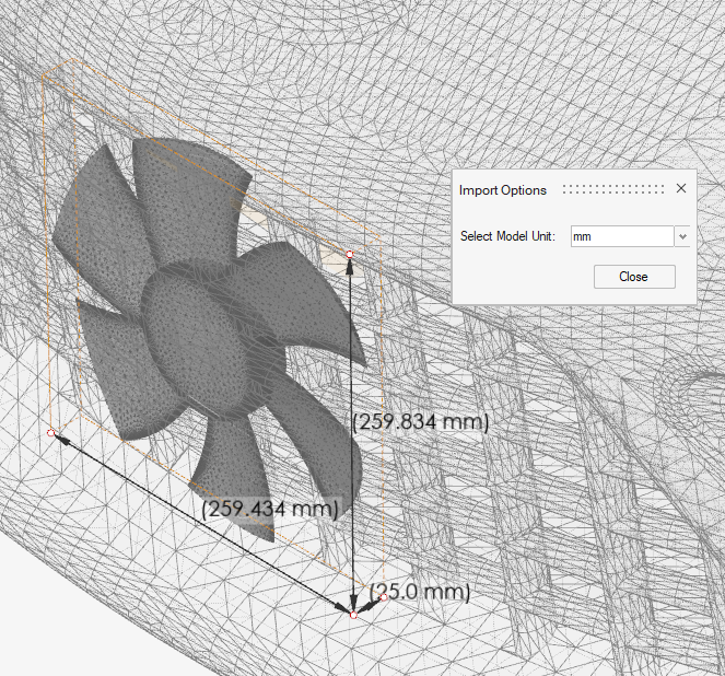
Figure 6. - Multiple Measurements on the Same Part
- Multiple outputs of the same type (for example, monitoring surface) can now be defined using the same part. The measurements are shown as a legend for the selected part in the modeling window.
- Demo Browser
- The Demo browser can be used to access bundled demo models from the UI
and is also accessible through Python API for scripts.
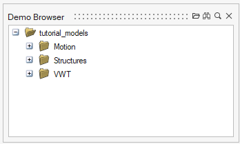
Figure 7. - Mesh Information
- Mesh information, such as the number of vertices and triangles, can be
queried with the
meshInfo()python API.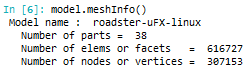
Figure 8. - Output Controls
- The new mesh_data variable has been added to the full data output.
- Precision Control of Numbers
- The new Number Format settings in Preferences can be used to control the display format of numbers in the UI.
Resolved Issues
- Part names can now contain the period (.) character.
- XML import/export errors have been fixed for:
- Incorrect time steps
- Turbulence zones
- Global wall model intensity for one-way coupling
- Fan speed is now correctly exported in rpm units instead of rad/s.
- Fan speed has been updated correctly for Overset fan part.
- Reset ride height now works correctly when the Wind Tunnel is present.
- Overset volumes for fans are now checked for leaks to prevent containment check errors.
- Moving or rotating Overset volumes no longer results in deletion.
- Memory leak on deleting a fan part with Overset mesh has been fixed.
- Editing number of layers for offset mesh controls from the Property editor now works correctly.
- Parts with errors in the geometry are no longer lost when saving to a .vwt file.
Known Issues
- Performing an undo operation while using the fan guide panel can result in an invalid state.
Altair Virtual Wind Tunnel for ultraFluidX 2022.2 Release Notes
Highlights
Virtual Wind Tunnel 2022.2 brings the following enhancements:
- Tesselation control for geometry parts
- Sub-time step support for monitoring surfaces
- Robust Boolean checks for closed parts
- Python API demos
New Features
- Real-time Tessellation Control
- This feature enables a "direct from CAD" workflow when dealing with
geometry parts. Geometry parts that need to be tessellated as STL parts
can be more precisely controlled. Every geometry part has independent
tessellation parameters. You can edit these settings to see a live
rendering of the tessellation and adjust the settings on the
go.Note: This feature does not create a continuous surface mesh across parts, but rather an independent triangulation on each one. It is the user's responsibility to ensure that the CAD model and the resulting tessellation is suitable for simulation and does not contain large gaps or intersections.
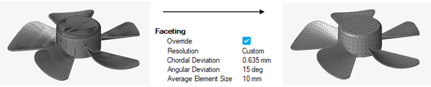
Figure 9. - Python API Demos
- An interactive Python demo tool has been added to the Help menu.
Snippets of Inspire and VWT Python API can be run in the demo window as
a live tutorial with edits. These snippets can be copied to the Python
window and run as part of a larger project setup. These demos help the
user to learn and understand the python API as they build scripts to
automate setup with VWT in batch mode.
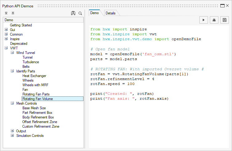
Figure 10.
Enhancements
- Sub-Time Step Support for Monitoring Surfaces
- Monitoring surfaces now support sub-time step output frequencies making
their use identical to all other output settings. Both Visual and
Summary output modes now support fractional Output Intervals. They can
also be computed from user requested Refinement level or Target
frequency.
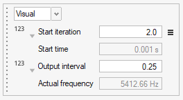
Figure 11. - Boolean Checks for Closed Parts
- In previous releases of Virtual Wind Tunnel, Boolean checks on multi-part volumes produced a warning due to the presence of unstitched edges between the parts. The closed part logic has been modified to first Boolean the input parts, then check for a closed volume. It can now correctly identify multiple surfaces that form a closed volume and work with non-conformal edges. The check is used to verify Heat Exchanger parts, MRF and OSM volumes, and custom refinement zones.
Resolved Issues
- Boundary Layer settings are correctly saved in vwt format.
- Turbulence zones are correctly exported and imported as xml templates.
- Editing section cut normal does not result in errors if set to (0,0,0).
- Averaging window is recomputed correctly on changing the unit system.
- Updating far-field mesh size updates the output start time and frequency correctly.
- Output interval is exported with high precision and no longer rounded to 6 decimal places.
- Nastran file format is no longer supported as an export option.
Altair Virtual Wind Tunnel for ultraFluidX 2022.1 Release Notes
Highlights
Virtual Wind Tunnel 2022.1 introduces:
- Arbitrary axis support for section cuts and fans with overset mesh volume.
- Expanded Python API support for Virtual Wind Tunnel.
Enhancements
- Arbitrary Axis Support for Overset Mesh
- Fan parts are no longer required to be aligned to primary axes. The axis
of rotation is automatically computed. The cylindrical overset mesh
volume is now computed with a more robust algorithm and the accuracy of
the radius is vastly improved.
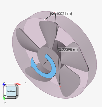
Figure 12. - Arbitrary Axis Support for Section Cuts
- Section cut plane can also be assigned an arbitrary axis. The plane move
tool now supports rotation and the plane edges can be selected to
resize.
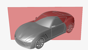
Figure 13. - Fan Overset Volume Workflow
- The Boolean operation from the split intersected parts options and containment check algorithms have been enhanced. This should result in higher quality splits and better containment checks for discrete STL parts. Fan parts that are imported as geometry use a geometry workflow and are not tessellated into STL parts during split operations. This results in a high fidelity representation for geometry parts.
- Python API
- Virtual Wind Tunnel now supports more features that can be programmed
via Python API. Using the VWT Python API simplifies automating a Design
of Experiments study. VWT Python API is compatible with and builds on
top of the Inspire Python API. Utilize the Inspire API to enhance how
you interact with Virtual Wind Tunnel.Note: The current recommendation is use either the graphical tools or the python API from the Python window to setup a simulation, not both.
Resolved Issues
- Fan axis accuracy for STL parts has been improved.
- Fan parts inside an overset volume can now be assigned Surface output and Offset mesh refinement.
- Containment check works better with non-cylindrical overset volumes and correctly identifies parts.
- Moment system is correctly exported and imported to and from .xml template files.
- Passive part definitions are saved correctly in .vwt file.
- Pop-up warnings for missing parts in template file have been re-enabled.
- Drop-down menu for monitoring surfaces in the output table view is no longer editable.
- Units for output interval no longer displays as Hz.
Altair Virtual Wind Tunnel for ultraFluidX 2022 Release Notes
Highlights
Virtual Wind Tunnel 2022 brings significant improvements when working with STL files and adds features towards the needs of aero-acoustics simulations.
Highlights include:
- Improved performance with STL files
- Higher frequency sampling through sub-time step support
- User friendly output control with an updated microdialog and table view
- Improvements to support fan noise simulations
- Visualization support via HyperWorks CFD Post
- Improved batch capability
New Features
- Improved performance with STL files
- A new, lightweight triangle-based model representation dramatically improves STL file I/O performance, especially for large models. Model import and load times are now twice as fast. Vwt/stmod file save time is three to four times faster for large model files. File sizes and application memory usage have been reduced to half the previous usage.
- Improved batch capability
- Virtual Wind Tunnel can now be launched in batch mode with and without the GUI. Batch mode enables you to import a model, import and apply a full simulation template, and export simulation files. These output files can subsequently be run with ultraFluidX.
Enhancements
- Higher frequency sampling through sub-time step support
- ultraFluidX allows much finer output data from refined mesh regions in
the form of fractional output intervals. These are now specified in
floating point format. These are automatically rounded to the nearest
supported fractions. A new microdialog shows the output interval
specified as 0.25 below that corresponds to the fraction ¼. The
corresponding physical frequency is also shown as a visual aid.
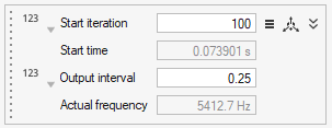
Figure 14. - Improved output control
- Post-processing data output controls now allow unit-based inputs, in
addition to solver-based iterations. Start time for recording outputs
can be specified in physical time or solver iterations. High frequency
sampling via sub-time steps is supported through three input choices:
- Fractional output intervals
- Mesh refinement levels
- Frequency-based input
- As shown previously, the microdialog for outputs has been enhanced so
you can select your preferred input mode. Choosing the clock icon on the
top left will allow you to a input start time in seconds, as shown
below. Instead of fractional output interval, you can specify the mesh
refinement level by selecting the mesh icon in the left center to set
the correct fractional output interval.
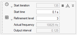
Figure 15. - Alternatively, you can select the Hz icon to directly specify your
preferred sampling frequency in Hertz. This input is automatically
rounded to the closest fraction supported by the solver and mesh
refinement level. The actual sampling frequency and fractional output
interval are shown right below the user requested target frequency.
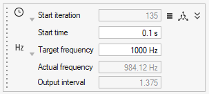
Figure 16. - While all outputs support this new microdialog design, monitoring
surface has a subtle difference. Since it doesn’t support fractional
output intervals, calculations are rounded to whole numbers and mesh
refinement level selector is unavailable. In addition, it uses a
drop-down menu to select Visual and Summary output modes. Previously,
the Visual and Summary outputs were stacked one below the other.
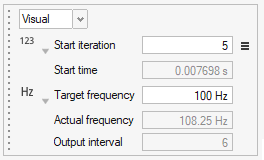
Figure 17. - The Output Table view allows you to work with all this information in
the same window. Multiple outputs can be selected in this view which
makes bulk changes easy to perform.
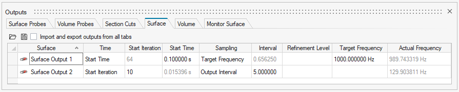
Figure 18. - Simulation mode to support Fan Noise simulations
- A simulation mode has been introduced in the Run dialog that can be used to indicate you are performing a fan noise simulation. This tells the ultraFluidX solver to automatically reconfigure default settings from external aerodynamics to fan noise and saves the user from having to do them manually.
- Smooth ramp up for fans
- The simulation can now be smoothly ramped up with user specified
iterations in the Run dialog. This smoothly
increases the fan rotation speed and inflow velocity for the Wind
Tunnel.
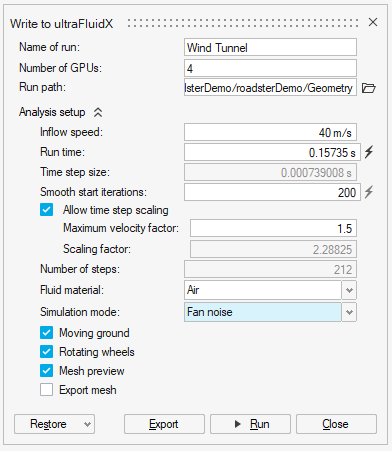
Figure 19. - Support for precision and scientific notation for Probe output data
- As part of enhancements needed to improve fan noise simulations, probe output data is now written out in scientific notation and the output data precision has been increased to eight significant digits. You can override these settings in the Output Controls panel.
- Improved default settings
- The default window-averaging window size is now computed as a function
of inflow velocity and object length.
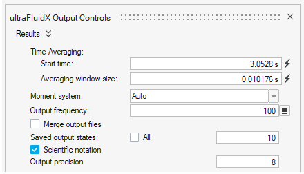
Figure 20. - Visualize results with HyperWorks CFD Post
- The uFX results files can now be visualized in HyperWorks CFD Post. The
Show Analysis button will prompt you to select
*.case or *.sos files that
are then loaded into HyperWorks CFD Post. HyperWorks Desktop will need
to be installed separately for this to function seamlessly. This
replaces Fieldview which is no longer available from within Virtual Wind
Tunnel.
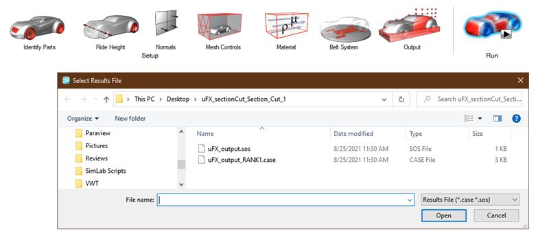
Figure 21. - Support for binary STL files
- Binary STL files can now be imported into Virtual Wind Tunnel. Note that binary STLs do not support multiple parts or names in a single file. All triangles in a single binary file are imported as a single part.
Known Issues
The following known issues will be addressed in a future release as we continuously
improve performance of the software:
- Modifying units on importing STL/NAS files.
- In rare occasions selecting the split intersected parts advanced option for a fan overset mesh volume can cause errors.
Resolved Issues
- Divide by zero errors are protected in case of zero inflow velocity.
- Run settings are saved correctly in the *.vwt database format.
- Deleted section cuts do not reappear as solid objects on reloading vwt file.
- Probes created on overset volume no longer gets transformed into Point objects.
- Custom mesh control zones do not intersect with overset volume.
- False positive on fan volume check containment has been fixed.
- Run path does not get reset to simulation folder when Export model in run path setting is turned on.
- Panel layout of a VWT session is recalled correctly.
- Gap finder tool has been removed.