
Shape
Visualizing an elementary object with variable size; all data have to be set as modifiers (see info layer)
![]()
Library
Modelica/Mechanics/MultiBody/Visualizers/Advanced
Description
Model Shape defines a visual shape that isshown at the location of its reference coordinate system, called'object frame' below. All describing variables suchas size and color can vary dynamically (with the only exceptionof parameter shapeType). The default equations in thedeclarations should be modified by providing appropriate modifierequations. Model Shape is usually used as a basic building block toimplement simpler to use graphical components.
The following shapes are supported viaparameter shapeType (e.g., shapeType="box"):

The dark blue arrows in the figure above are directed alongvariable lengthDirection. The light blue arrows are directedalong variable widthDirection. The coordinate systemsin the figure represent frame_a of the Shape component.
Additionally, external shapes can be specified as (not all options might be supported by all tools):
- "1", "2", …
define external shapes specified in DXF format in files "1.dxf", "2.dxf", … The DXF-files must be found either in the current directory or in the directory where the Shape instance is stored that references the DXF file. This (very limited) option should not be used for new models. Example:
shapeType="1". - "modelica://<Modelica-name>/<relative-path-file-name>"
characterizes the file that is stored under the location of the <Modelica-name> library path with the given relative file name. Example:
shapeType = "../../../../../Resources/Data/Shapes/Engine/piston.dxf". - "file://<absolute-file-name>"
characterizes an absolute file name in the file system. Example:
shapeType="file://C:/users/myname/shapes/piston.dxf".
The supported file formats are tool dependent. Most tools support at least DXF-filesbut may support other format as well (such as stl, obj, 3ds).Since visualization files contain color and other data, the correspondinginformation in the model is usually ignored.For information about DXF files, see Wikipedia.As a default it is assumed that the DXF coordinates are in the "frame_a"-system and in meters, and that the 3dfaces are two-sided.Some tools support only 3dface (for geometry) and layer (for advanced coloring).
The sizes of any of the above components are specified by thelength, width and height variables.Via variable extra additional data can be defined:
| shapeType | Meaning of parameter extra |
|---|---|
| "cylinder" | if extra > 0, a black line is included in the cylinder to show the rotation of it. |
| "cone" | extra = diameter-left-side / diameter-right-side, i.e., extra = 1: cylinder extra = 0: "real" cone. |
| "pipe" | extra = outer-diameter / inner-diameter, i.e, extra = 1: cylinder that is completely hollow extra = 0: cylinder without a hole. |
| "gearwheel" | extra is the number of teeth of the (external) gear.If extra < 0, an internal gear is visualized with |extra| teeth.The axis of the gearwheel is along "lengthDirection", and usually:width = height = 2*radiusOfGearWheel. |
| "spring" | extra is the number of windings of the spring. Additionally, "height" is not the "height" but 2*coil-width. |
| external shape | extra = 0: Visualization from file is not scaled. extra = 1: Visualization from file is scaled with "length", "width" and "height" of the shape |
Parameter color is a vector with 3 elements,{r, g, b}, and specifies the color of the shape.{r, g, b} are the "red", "green" and "blue" color parts.Note, r, g, b are given as Integer[3] in the ranges 0 … 255,respectively. The predefined typeMultiBody.Types.Color contains a menudefinition of the colors used in the MultiBody library together with a color editor.
The dialog variables shapeType, R, r, r_shape,lengthDirection, widthDirection, length, width,height, extra, color, and specularCoefficientare declared as (time varying) input variables.If the default equation is not appropriate, a correspondingmodifier equation has to be provided in themodel where a Shape instance is used, e.g., in the form
Visualizers.Advanced.Shape shape(length = sin(time));
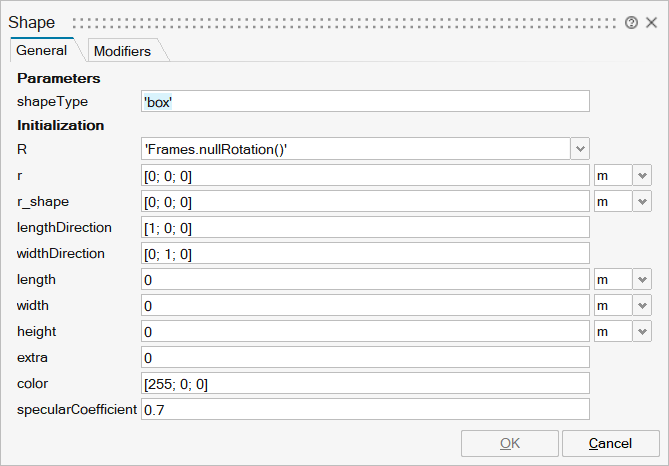
Parameters
| Name | Label | Description | Data Type | Valid Values |
|---|---|---|---|---|
mo_shapeType | shapeType | Type of shape (box, sphere, cylinder, pipecylinder, cone, pipe, beam, gearwheel, spring, <external shape>) | String | |
mo_R | R | Orientation object to rotate the world frame into the object frame | FromModelica('Modelica.Mechanics.MultiBody.Frames.Orientation') | |
mo_r | r | Position vector from origin of world frame to origin of object frame, resolved in world frame | Vector of size 3 | |
mo_r_shape | r_shape | Position vector from origin of object frame to shape origin, resolved in object frame | Vector of size 3 | |
mo_lengthDirection | lengthDirection | Vector in length direction, resolved in object frame | Vector of size 3 | |
mo_widthDirection | widthDirection | Vector in width direction, resolved in object frame | Vector of size 3 | |
mo_length | length | Length of visual object | Scalar | |
mo_width | width | Width of visual object | Scalar | |
mo_height | height | Height of visual object | Scalar | |
mo_extra | extra | Additional size data for some of the shape types | Scalar | |
mo_color | color | Color of shape | Vector of size 3 | |
mo_specularCoefficient | specularCoefficient | Reflection of ambient light (= 0: light is completely absorbed) | Scalar |
| Name | Label | Description | Data Type | Valid Values |
|---|---|---|---|---|
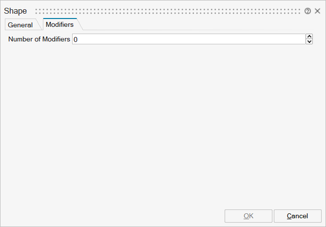
mo__nmodifiers | Number of Modifiers | Specifies the number of modifiers | Number | |
mo__modifiers | Modifiers | Add new modifier | Structure | |
mo__modifiers/varname | Variable name | Cell of strings | ||
mo__modifiers/attribute | Attribute | Cell of strings | 'start' | |
mo__modifiers/value | Value |