
SignalPWM
Generates a pulse width modulated (PWM) boolean fire signal
![]()
Library
Modelica/Electrical/PowerConverters/DCDC/Control
Description
This controller can be used both for DC/DC and AC/DC converters.The signal input of the PWM controller is the duty cycle; the duty cycle is the ratio of the on timeto the switching period. The output firing signal is strictly determined by the actual duty cycle, indicated as d in Fig. 1.
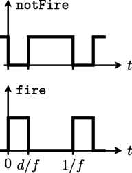 |
The firing signal is generated by comparing the sampled duty cycle input with a periodic saw tooth signal [Williams2006].
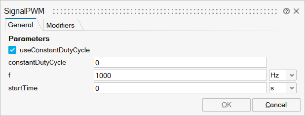
Parameters
| Name | Label | Description | Data Type | Valid Values |
|---|---|---|---|---|
mo_useConstantDutyCycle | useConstantDutyCycle | Enables constant duty cycle | Number | 0 |
mo_constantDutyCycle | constantDutyCycle | Constant duty cycle | Scalar | |
mo_f | f | Switching frequency | Scalar | |
mo_startTime | startTime | Start time | Scalar |
| Name | Label | Description | Data Type | Valid Values |
|---|---|---|---|---|
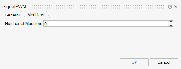
mo__nmodifiers | Number of Modifiers | Specifies the number of modifiers | Number | |
mo__modifiers | Modifiers | Add new modifier | Structure | |
mo__modifiers/varname | Variable name | Cell of strings | ||
mo__modifiers/attribute | Attribute | Cell of strings | 'start' | |
mo__modifiers/value | Value |
Ports
| Name | Type | Description | IO Type | Number |
|---|---|---|---|---|
fire | implicit | Firing PWM signal | output | 1 |
notFire | implicit | Firing PWM signal | output | 2 |
Port 3 | implicit | Duty cycle | input | 1-mo_useConstantDutyCycle |