
Tutorial: Set Up and Run a PolyFoam Simulation
Tutorial Level: Beginner Run a simulation to assess the feasibility and optimize the manufacturing process of a polyurethane part.
- Run a test to understand the properties of the foaming material.
- Define the part and tooling from imported CAD geometry.
- Define the parameters for the foaming process.
- Simulate the foaming process for the part design.
- Review simulation results to understand where the part succeeds and fails.
Access Files for the Tutorial
To access files, select and navigate to
<installation_directory>/tutorial_models/.
Run a Pouring Cup Test
-
Hover over the Foam Part icon and click the
Pouring Basin.

The default cylinder basin appears. -
From the microdialog, select the cone shape for the
basin, then click the chevron
 to expand the parameters for the basin.
-
Enter these parameter values:
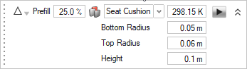
Your basin setup should look something like this: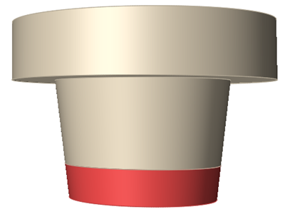
-
Click the Run button on the microdialog to run the
pouring cup test.
The test shows you how parameters such as temperature and fill percentage can determine the foaming behavior of the material for a particular mold shape. The simulated expansion of the foam can help you determine the optimal conditions and material amounts to use in the physical manufacturing of the foam part.
Define the Foam Part in the CAD Geometry
- From the menu bar, select .
-
Browse to your working directory, select foam_test.x_b,
and click Open.
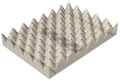
The model opens in the modeling window.
-
Click the Foam Part icon.

-
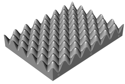
Click the part component in the CAD geometry to designate it as the foam
part.
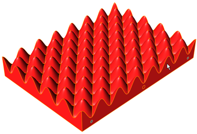
- For the initial temperature of the part, enter 298.15K in the microdialog.
-
Right-click twice to confirm the part selection.
The designated foam part should look something like this:
-
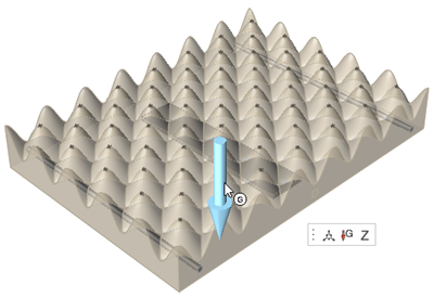
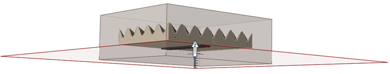
On the Part icon, click Gravity
Direction.

-
Keep the default gravity setting. Left-click the Gravity arrow, then
right-click twice to confirm.
Create a Nozzle Path for the Foaming Material
-
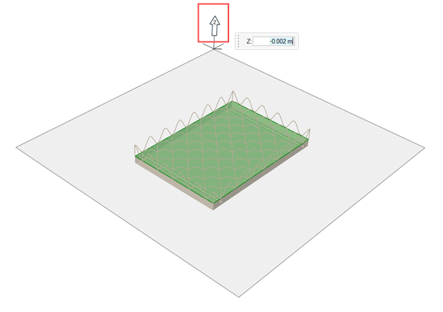
Click the Nozzle icon.

A plane appears for you to define the location of the nozzle relative to the part. -
Click and drag the Move tool to adjust the plane to Z: .025
m or enter the value in the microdialog.
Tip: Zoom out the view of your model if the Move tool is not visible.
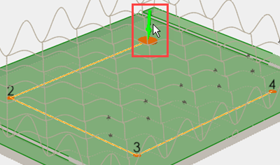
- Click on the plane to place the first point of the nozzle path.
- Select the Path check box in the microdialog to indicate that you want to create a path rather than a fixed point for the nozzle.
-
Place three more points to create a path in the shape of an open rectangle.
Right-click after you place the fourth point.
The path shape does not need to be precise at this point. You will refine it in the next step.
-
Click the move button
 in
the microdialog for point 1 of the path.
in
the microdialog for point 1 of the path.
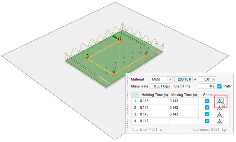
The coordinates for that point appear in the microdialog. Enter new coordinates for point 1 from the following table, then right click to bring back the nozzle microdialog. Modify the remaining 3 points of the nozzle path.For this point Enter these coordinates 1 X: -.150m, Y: .220 m, Z: .010 m 2 X: -.350 m, Y: .220 m, Z: .010 m 3 X: -.350 m, Y: .060 m, Z: .010 m 4 X: -.150 m, Y: .060 m, Z: .010 m -
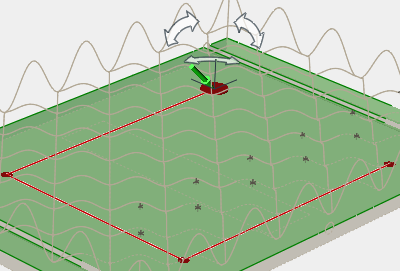
Double-click the green arrow to modify the foam injection direction.
-
Change the direction to X: 1, Y: 0, Z: -1 in the
microdialog or manipulate the direction with the Move tool.
-
Right-click to bring back the microdialog and change the nozzle radius
(R) to .015m. Keep the default
values for the remaining parameters.
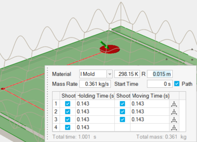
- Right-click twice to confirm the nozzle path.
Define the Tooling for the Part
-
Click the Tooling icon.

-
Click Insert from the secondary ribbon.

-
Select the inserts in the model.
- In the microdialog, change the material to IsoPink_Special, change the temperature to 299.15K, then right-click twice to confirm and exit.
Create the Mold for the Part
-
Click the Tooling icon.
-
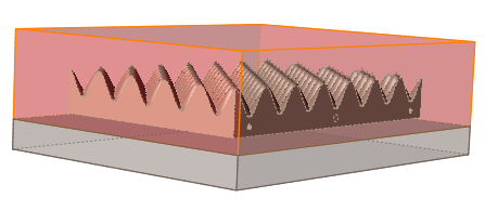
Click the Mold icon from the secondary ribbon.

A mold that is 30% larger than the part is automatically created.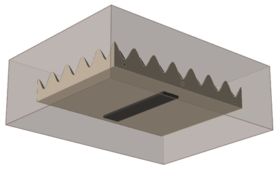
-
On the Mold icon, click the Split Mold satellite, and
zoom out with the scroll wheel until you can see the Move tool.

-
Click the Z arrow on the Move tool and enter Z:
-0.025 in the microdialog.
- Click Cut on the microdialog to split the mold.
-
The portion of the mold above the cut line is selected. For this section of the
mold, change the material to ADC10 and the temperature to
318.15 K.
- Right-click twice to confirm and exit the tool.
Add Vents to the Part and Mold
-
Click the Point Vent icon.

-
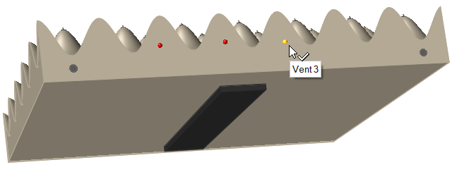
Click three locations on the front face to create three point vents.
-
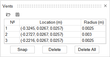
On the Vents icon, click the List Vents satellite.

The table shows the current coordinates and radius for each vent. Column 1 numbers the vents in the order that you created them. -
To modify the vents, click a vent number from column one, then enter the
coordinates for the Location and the
Radius of each vent in the table. Modify each vent as
follows:
- Close the Vents table.
-
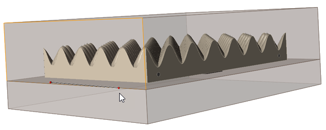
On the Vents icon, click the Line Vent satellite.

-
On the mold, click and drag to sketch a line vent. Click again to end the
vent.
- For the line vent Thickness, enter .002 in the microdialog.
-
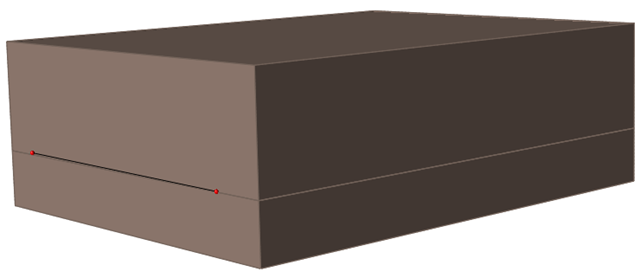
To change the location of the line vent, click the move button in the microdialog, then enter the following
coordinates for the start and end points of the line vent.
For this point Enter these coordinates 1 X: -.468 m, Y: .024 m, Z: .000 m 2 X: -.468 m, Y: .031 m, Z: .000 m -
Right-click twice to confirm and exit.
The new line should be close to the parting line of the mold and look something like this:
Define the Process Parameters for the Simulation
-
Click the Process icon.

- For Gelling rate, enter 60%.
- Keep the defaults for the remaining parameters, then click OK.
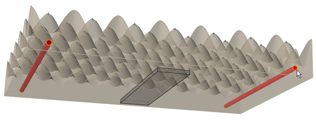
Simulate and Validate the Foaming Process
-
On the Analysis icon, click Run
Analysis.

The Run Analysis dialog appears. Keep the defaults for the analysis. - Click Run to start the simulation.
-
When the simulation is complete, view the results in the Analysis
Explorer.
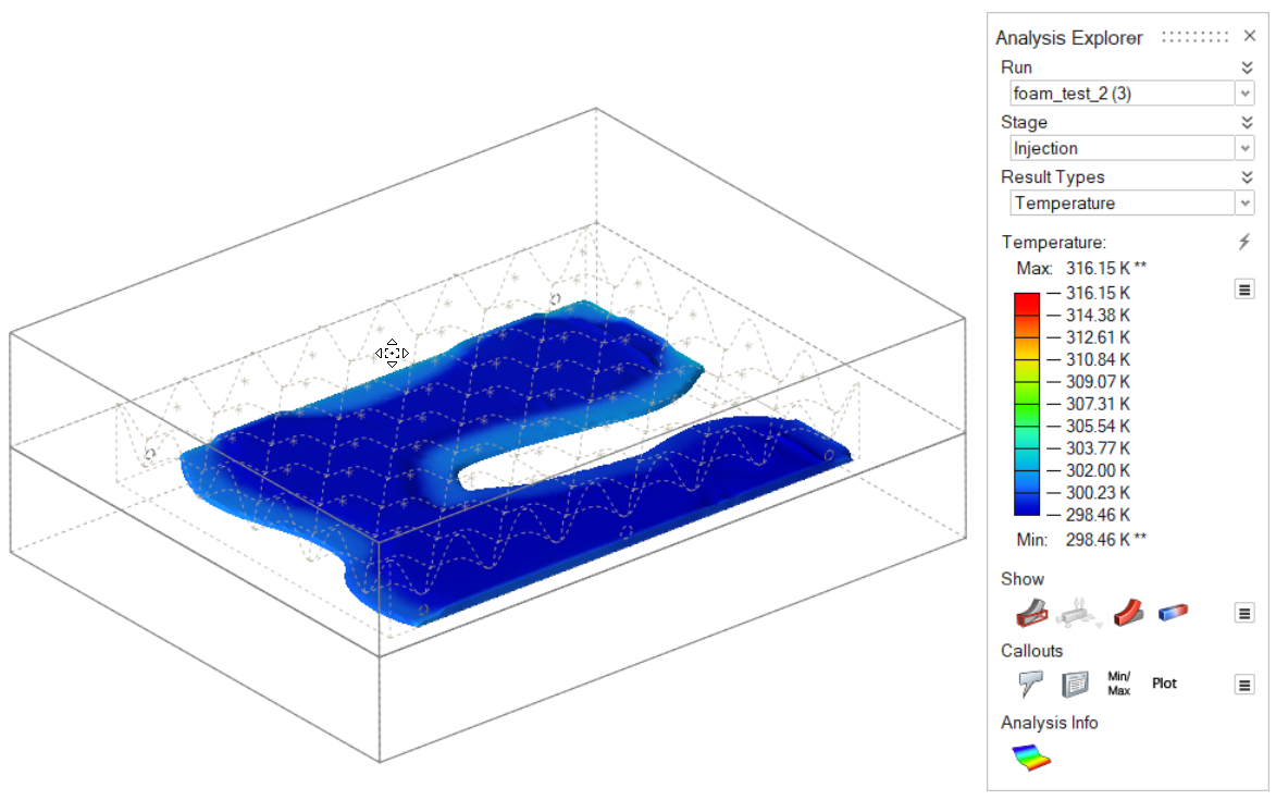
The results help you understand where the part design can be modified. The simulation can be repeated until an ideal part design is achieved.