
Fluid Part
Use the Fluid Part tools to designate or create the fluid parts in your model geometry.
A fluid part is a designated volume that dispensed fluid may flow into. You might want to fill the fluid part entirely with fluid material, or you may want to merely indicate areas that dispensed fluid might reach.
Designate a Fluid Part
If your model geometry contains one or more parts that represent a fluid part in the finished product, use the Fluid Part tool to designate them as fluid parts.
-
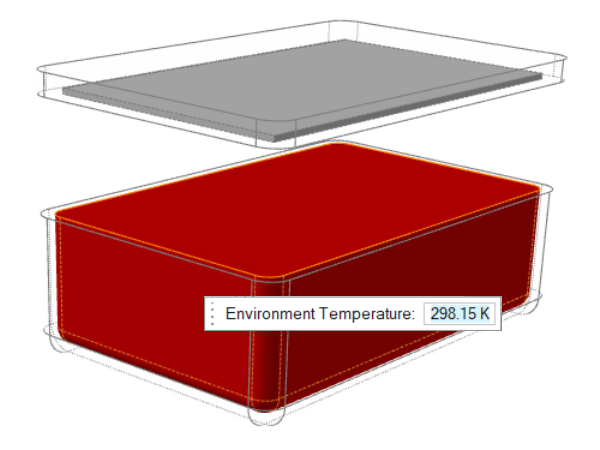
Click the Fluid Part icon.

-
Select the fluid part in your model.

The selected part is displayed in transparent red. - Optional: Change the Environment Temperature if necessary.
-
Click the Gravity Direction icon to set the gravity
direction with respect to the part.

-
Use the microdialog options to flip or rotate the model to align it with the
gravity direction. The gravity direction affects the behavior of the liquid as
it is dispensed into the model and during solidification.
Microdialog option Description 
Rotate the model with the Move tool. 
Pick a surface to align its normal with the gravity direction. 
Flip the model vertically to switch the model between the positive and negative Z direction.
Create a Fluid Part
Select one or more voids in your model to designate them as fluid domains.
-
Click the Create Fluid Domain icon.

-
If you have not yet selected a housing part,
-
Click the
 button to
confirm.
Voids in all selected parts appear red.
button to
confirm.
Voids in all selected parts appear red.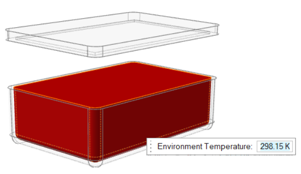
-
Click the
-
If you have already selected a housing part,
-
Housings will be selected by default on the
guidebar. A void in one of the designated housing parts will appear red.
All other voids will appear gray.
- Optional: Control-click to select more voids. Shift-click to deselect.
- Optional: Use the microdialog to change temperature of the working environment.
-
When you are satified with the selections, click the
 button to accept and close the tool.
-
Housings will be selected by default on the
guidebar. A void in one of the designated housing parts will appear red.
All other voids will appear gray.