Add
After selecting the Add option the following panel will be shown on the right side of the window:
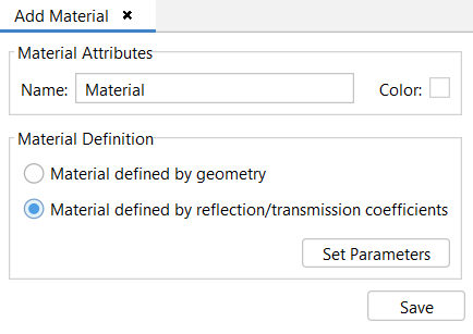
This option allows the user to create a new material. The following options are available:
Material Attributes-Name: The user may want to provide a name for this material for future reference.
Material Attributes-Color: For more information, see APPENDIX A: Color Selection.
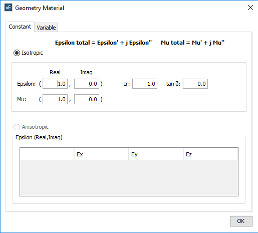
Material Definition - Material defined by geometry: Used to define a material according to its physical properties. After clicking on the Set Parameters button, two different options are available in the Material defined by Geometry window:
- Constant
§ Real part: common values are greater than or equal to 1.0.
§ Imaginary part: if the imaginary part is negative, the material is considered to have losses; otherwise it would be equivalent to a material with gain.
o Isotropic: Selecting this option sets the epsilon (e’ - permittivity) and mu (µ’ - permeability) properties immutable. The user will need to specify both real and imaginary components of both properties or loss tangent and relative permittivity. Common real values for epsilon and mu are greater of equal to 1.0. If the imaginary part is negative, the material is considered to have losses; otherwise, it’s considered to be a material with gain.
o Anisotropic: This option allows the user to set the material properties depending on the volumetric subdomain direction (i.e. the dielectric coefficient may change depending on the direction of the subdomains). The epsilon parameter consists of a 3x3 matrix where all Cartesian combinations can be modified. The materials using this option are only designed to be applied to volumes.
- Variable
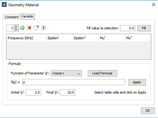
To assign the physical properties of the material according to the frequency.
§ Frequency (in GHz): Sets the associated frequency to the physical properties. The frequency values for each material are interpolated when the simulation is launched in order to use the most suitable one for the working frequency.
§ Real part (’): common values are greater than or equal to 1.0.
§ Imaginary part (’’): if the imaginary part is negative, the material is considered to have losses; otherwise it would be equivalent to a material with gain.

§ Remove: to remove existing frequencies to the material properties
§ Import/Export: to import table with values from a text file or export the table into a text file.
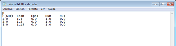
The information of this file can be modified by the user. Be sure not to modify the format and not to introduce any additional line break.

§ Fill value to selection: This option allows the user to automatically change the value of the selected cells of the table with the inserted value
These parameters can also be set using formulas in function of the frequency values.
§ Formula:
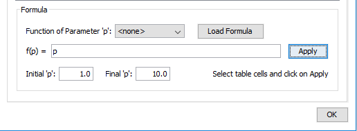
This option serves for completing the selected cells of the table with values depending on the selected function. After choosing the function that we want to apply, pressing the Load Formula button will load the formula f(p) in the field. The next step is choosing the initial and the final value for the function. The final step is selecting the cells that we want to apply the function to and press the button Apply. The cells will be auto-completed with the values created by the chosen function starting with the initial value and ending with the final one.
Material Definition - Material defined by reflection/transmission coefficients: Used to define a material according to its reflection coefficient. After clicking on the Set Parameters button, a window appears to define the reflection coefficient:
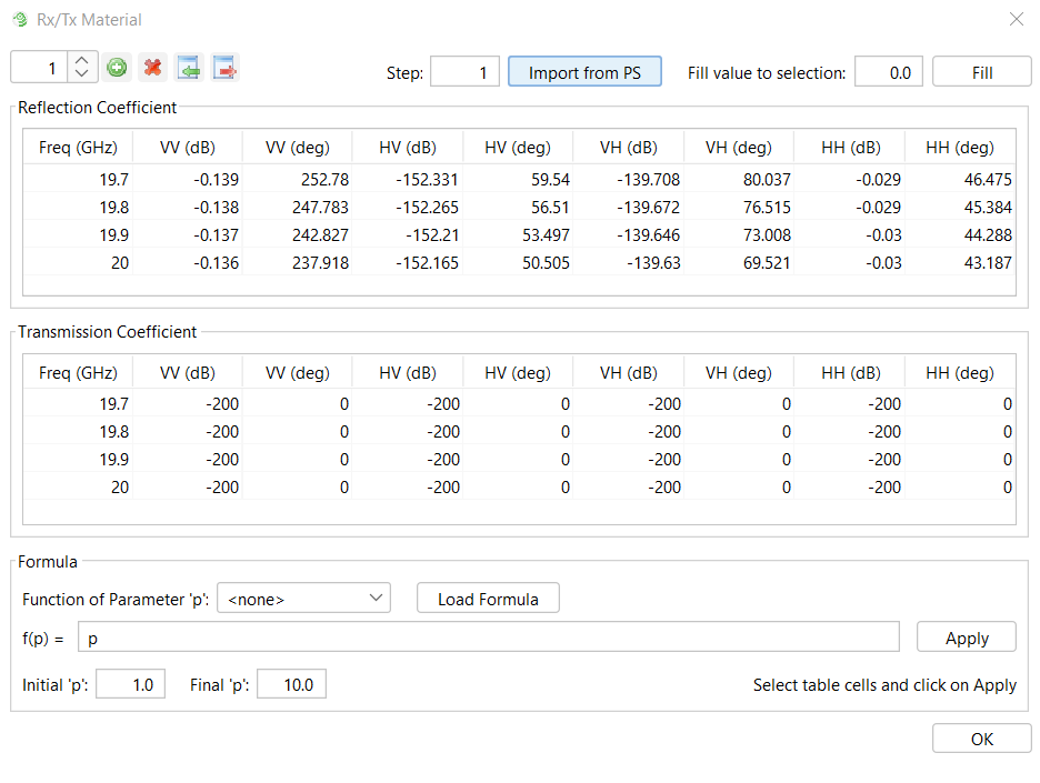
To assign the reflection and transmission coefficients according to the frequency.
- Frequency (GHz): Sets the associated frequency to the physical properties. The frequency values for each material are interpolated when the simulation is launched to use the most suitable one for the working frequency.
Import from PS: This option allows the user to import a matrix of reflections and transmission coefficients computed in the periodical structure module.
§ Fill value to selection: This option allows the user to automatically change the value of the selected cells of the table with the inserted value.
These parameters can also be set using formulas depending on the parameter p. Where p is defined from an initial value to a final value.
§ Formula:
This option serves for completing the selected cells of the table with values depending on the selected function. After choosing the function that we want to apply, pressing the Load Formula button will load the formula f(p) in the field. The next step is choosing the initial and the final value for the function. The final step is selecting the cells that we want to apply the function and pressing the button Apply. The cells will be auto-completed with the values created by the chosen function starting with the initial value and ending with the final one.