OS-E: 9000 Piezoelectric Analysis of a Cantilevered Bar

This example is used to demonstrate Piezoelectric Analysis using enforced voltage and enforced displacement using Linear Transient Analysis.

Model Files

Before you begin, copy the file(s) used in this example to your working directory.

Model Description

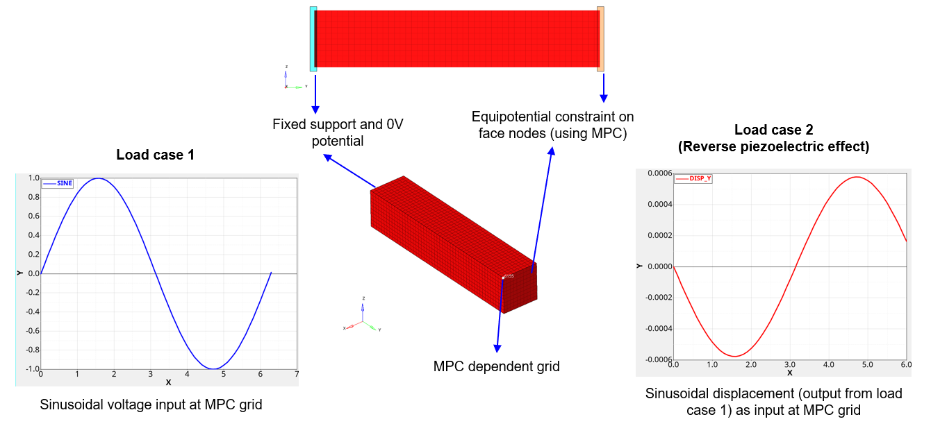
A cantilevered piezoelectric bar meshed with solid elements. In the first load case, the bar is subject to a sinusoidal electric potential at the free end. The applied potential triggers a structural deformation in the material. In the second load case, the output displacement from the previous load case is exported and added as input enforced displacement. This triggers the same voltage response, thereby demonstrating reverse piezoelectric effect.

Boundary Conditions

The boundary conditions defined in the model are as follows:
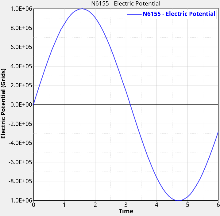
  • In load case 1, the sinusoidal voltage is scaled by an amplitude of 1000 kV and applied at the dependent grid of the MPC.
  • In load case 2, enforced displacement (exported from load case 1) is applied on the same MPC grid, to study the output voltage.


Figure 1. Boundary conditions used in the model

Material Properties

The material property definitions used in the model are as follows:
  • Anisotropic Dielectric matrix (MAT2PT)(1)
    PMTV = 1.505 0 0 0 1.301 0 0 0 1.505 10 8 farad/m MathType@MTEF@5@5@+= feaahqart1ev3aaatCvAUfeBSjuyZL2yd9gzLbvyNv2CaerbuLwBLn hiov2DGi1BTfMBaeXatLxBI9gBaerbd9wDYLwzYbItLDharqqtubsr 4rNCHbGeaGqiVu0Je9sqqrpepC0xbbL8F4rqqrFfpeea0xe9Lq=Jc9 vqaqpepm0xbba9pwe9Q8fs0=yqaqpepae9pg0FirpepeKkFr0xfr=x fr=xb9adbaqaaeGaciGaaiaabeqaamaabaabaaGcbaWaamWaaeaaca WGqbGaamytaiaadsfacaWGwbaacaGLBbGaayzxaaGaeyypa0ZaamWa aeaafaqabeWadaaabaGaaGymaiaac6cacaaI1aGaaGimaiaaiwdaae aacaaIWaaabaGaaGimaaqaaiaaicdaaeaacaaIXaGaaiOlaiaaioda caaIWaGaaGymaaqaaiaaicdaaeaacaaIWaaabaGaaGimaaqaaiaaig dacaGGUaGaaGynaiaaicdacaaI1aaaaaGaay5waiaaw2faaiaaigda caaIWaWaaWbaaSqabeaacqGHsislcaaI4aaaaOGaamOzaiaadggaca WGYbGaamyyaiaadsgacaGGVaGaamyBaaaa@572B@
  • Piezoelectric coupling matrix (MATPZO) – Strain charge form(2)
    PIEZO = 0 0 0 741 0 0 274 593 274 0 0 0 0 0 0 0 0 741 10 12 m/Volt MathType@MTEF@5@5@+= feaahqart1ev3aaatCvAUfeBSjuyZL2yd9gzLbvyNv2CaerbuLwBLn hiov2DGi1BTfMBaeXatLxBI9gBaerbd9wDYLwzYbItLDharqqtubsr 4rNCHbGeaGqiVu0Je9sqqrpepC0xbbL8F4rqqrFfpeea0xe9Lq=Jc9 vqaqpepm0xbba9pwe9Q8fs0=yqaqpepae9pg0FirpepeKkFr0xfr=x fr=xb9adbaqaaeGaciGaaiaabeqaamaabaabaaGcbaWaamWaaeaaca WGqbGaamysaiaadweacaWGAbGaam4taaGaay5waiaaw2faaiabg2da 9maadmaabaqbaeqabmGbaaaabaGaaGimaaqaaiaaicdaaeaacaaIWa aabaGaaG4naiaaisdacaaIXaaabaGaaGimaaqaaiaaicdaaeaacqGH sislcaaIYaGaaG4naiaaisdaaeaacaaI1aGaaGyoaiaaiodaaeaacq GHsislcaaIYaGaaG4naiaaisdaaeaacaaIWaaabaGaaGimaaqaaiaa icdaaeaacaaIWaaabaGaaGimaaqaaiaaicdaaeaacaaIWaaabaGaaG imaaqaaiaaiEdacaaI0aGaaGymaaaaaiaawUfacaGLDbaacaaIXaGa aGimamaaCaaaleqabaGaeyOeI0IaaGymaiaaikdaaaGccaWGTbGaai 4laiaadAfacaWGVbGaamiBaiaadshaaaa@5F03@
  • Orthotropic elasticity coefficients (MAT9OR)
    E1
    60.61 GPa
    E2
    48.31 GPa
    E3
    60.61 GPa
    V12
    0.512
    V13
    0.289
    V23
    0.512
    G12=G23
    23.0 GPa
    G23
    23.5 GPa

Results

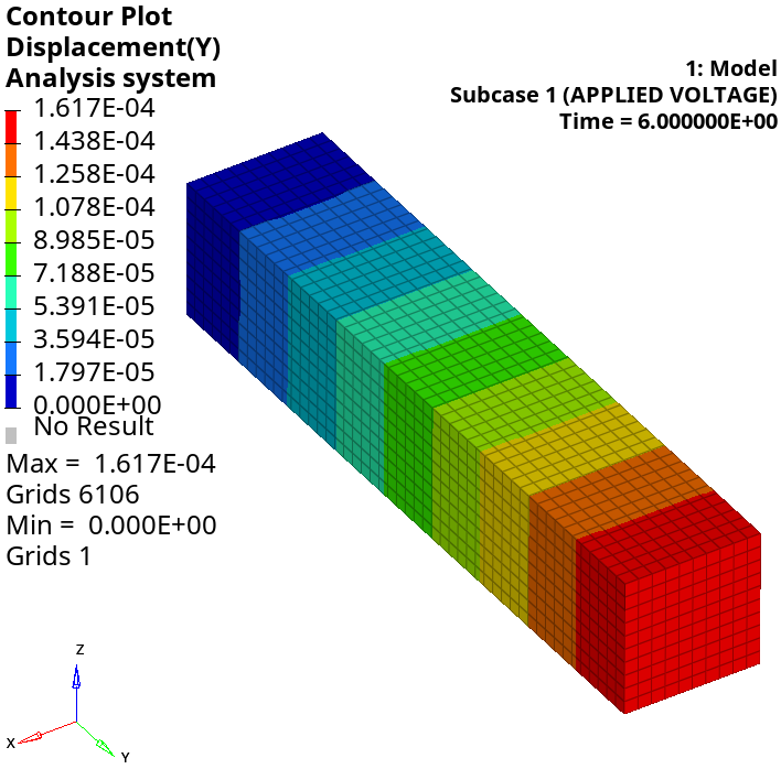
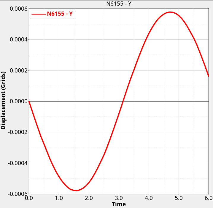
  • Load case 1: Applied sinusoidal voltage
    It can be noted that the applied voltage triggers a structural deformation which is also sinusoidal.


    Figure 2. Results for load case 1
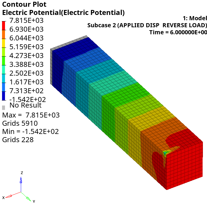
  • Load case 2: Reverse piezoelectric effect (applied displacement)
    It can be noted that the output electric potential (plotted at dependent grid of MPC) is identical to the applied voltage in load case 1, thereby demonstrating reverse piezoelectric effect.


    Figure 3. Results for load case 2