Create and Edit a Shell
A shell is a two-dimensional flat panel structural element that supports bending and in-plane deformation modes.
-
From the Model ribbon, click the tool.
Figure 1. 
-
From the guide bar, select the type of shell you wan to
create: Singly or Doubly.
Figure 2. 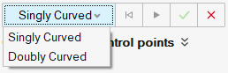
-
Create a shell.
-
After selecting more than two points, a microdialog is displayed that you can use to assign
properties,
 , and damping,
  .
.
Figure 3. 
Figure 4. 
Figure 5. 
-
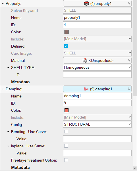
Click and assign properties and damping,
respectively. Click
 when finished.
-
From the guide bar, click
Create to create a shell.
Figure 6. 
The required parameters to create the shell subsystem are updated.
-
After selecting more than two points, a microdialog is displayed that you can use to assign
properties,
-
From the microdialog, click
 to edit the subsystem and update the parameters.
Figure 7. 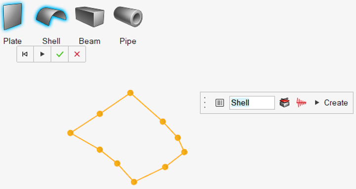
Figure 8. Shell Entity Editor 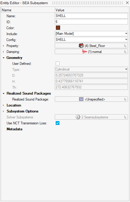
- Name
- Specify unique name.
- ID
- Specify unique ID.
- Config
- Specify the element type.
- Property
- Specify the property parameter based on the element type.
- Damping
- Specify damping to the subsystem.
- Geometry
- Based on the element type, update the geometry parameters.
- Generally, the geometry is automatically updated from the
user-defined geometry. You can modify the geometry information by
clicking User Defined as shown below.
Figure 9. 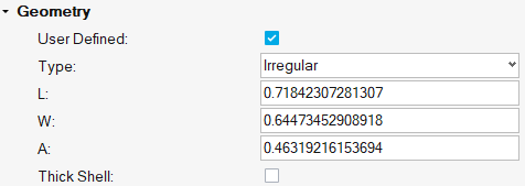
- Subsystem Options
- For experienced users, expand the Subsystem Options to change the default choices for the SEA Subsystems for all element types. For certain structural element types, use these options to adjust the default bending stiffness or conductance of the element and add non-structural mass, component mass, or fluid loading to the element when the options have been changed.
- Damping
- Assign a damping model to the element. From the Damping field
drop-down menu, select a damping model. This list contains all
predefined models which apply to the current element type. Click
 to display advanced damping options
that you can use to define additional damping models.
to display advanced damping options
that you can use to define additional damping models. - Properties
- Assign a property model to the element. From the Property field
drop-down menu, select a property model. The element materials and
cross-sectional parameters defined in the selected Property record
are displayed. Property records can be used to simplify the model
definition in cases where many elements have the same properties.
Click to display advanced property options
that you can use to define additional property models.
Figure 10.