Create Connections
Automatically and manually create connections.
Automatically Create Connections
-
From the SnRModelBuild ribbon, select the Create
Connections tool.
Figure 1. 
-
From the guide bar, select the connection type.
Figure 2. 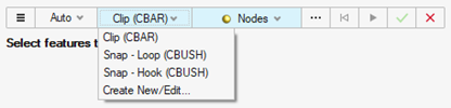
- From the guide bar, select Nodes, Features, or Solids.
-
In the modeling window, select the chosen entity to
create connections.
Tip: Use the middle mouse button to quickly navigate through the selections.
-
On the guide bar, complete one of the following:
- Click
 to apply and stay in the tool.
 - Click
 to apply and close the tool.
 - Click
 to exit the tool without applying.
- Click
- Nodes
- Selecting just one node around the clip hole is enough to generate the
connection.
Figure 3. Input 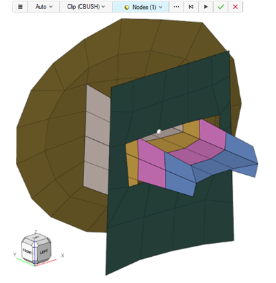
Figure 4. Output 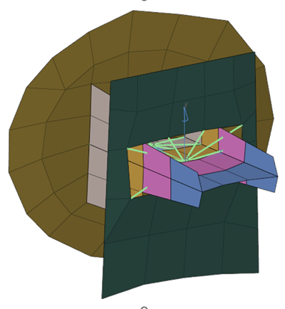
- Features
- Create multiple connections at once after detecting 2D holes using the
Features tool.
Figure 5. Input 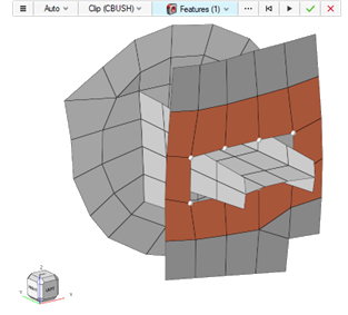
Figure 6. Output 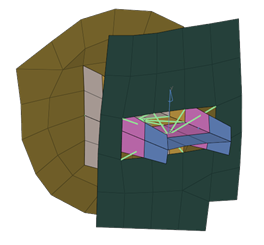
- Solids
- If clip geometry (CAD) is available, it can be used to generate connections
as well.
Figure 7. Input 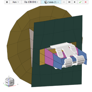
Figure 8. Output 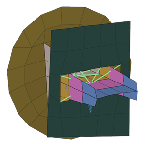
Manually Create Connections
-
From the SnRModelBuild ribbon, select the Create
Connections tool.
Figure 9.
- From the guide bar, select Manual.
- Select the connection type, CBUSH or CBAR.
-
If the connection type is CBUSH, you must also select the method for the Local
Coordinate System creation.
- Automatic A-B: the coordinate system is automatically defined based on the vector from node A to node B of CBUSH element.
- Select System: select a coordinate system that already exists in the model to be assigned to the CBUSH.
- Define System: define the coordinate system that will be assigned to the CBUSH by selecting its origin, axis and plane.
-
Select the elements that should be connected.
Tip: Use the Sync with Quick Selection option to quickly capture elements. From the guide bar, click
 to open advanced
selection. Select By Edge and Free loops
only to quickly capture the nodes around the hole using the
Alt key.
to open advanced
selection. Select By Edge and Free loops
only to quickly capture the nodes around the hole using the
Alt key.Figure 10. 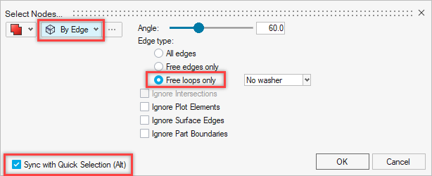
Figure 11. 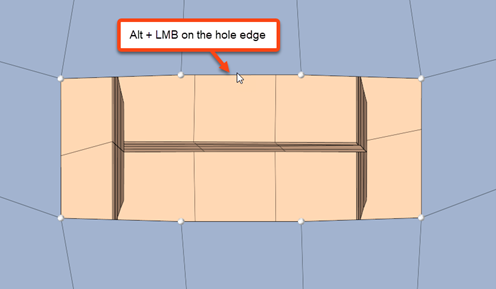
- Optional: If the connection type is CBUSH, select or define the coordinate system.
-
On the guide bar, complete one of the following:
- Click to apply and stay in the tool.
- Click to apply and close the tool.
- Click to exit the tool without applying.
- Click
- CBAR
-
Figure 12. Input 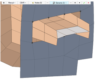
Figure 13. Output 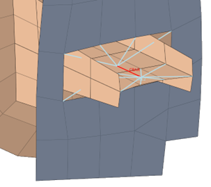
- CBUSH - Automatic A-B
- The coordinate system is automatically defined based on the vector from node
A to node B of CBUSH element.Note: Depending on the alignment of the input nodes/elements, the local coordinate system matches the other methods and requires no adjustment.
Figure 14. Input 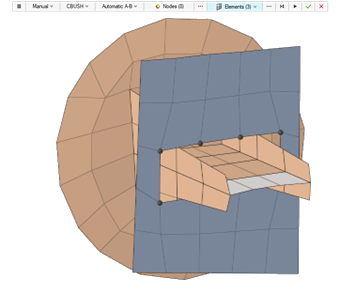
Figure 15. Output 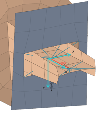
- CBUSH - Select System
- Select a coordinate system that already exists in the model to be assigned
to the CBUSH.
Figure 16. Input 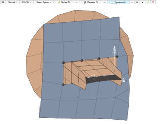
Figure 17. Output 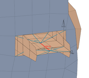
- CBUSH - Define System
- Define the coordinate system that will be assigned to the CBUSH by selecting
its origin, X-axis, and XY-plane.
Figure 18. Input 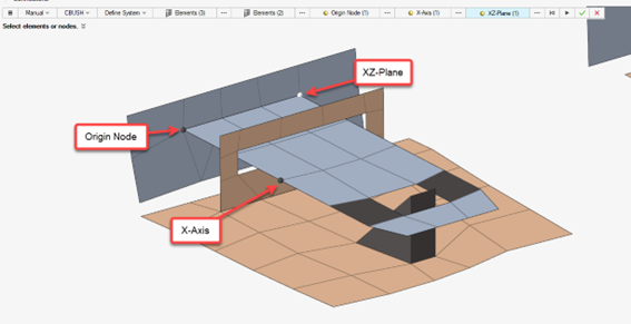
Figure 19. Output 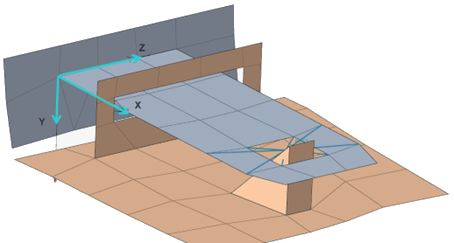
Connection Options
Define connection options, such as connections properties and adjacent RBE elements handling, via the Options dialog.
-
From the SnRModelBuild ribbon, select the Create
Connections tool.
Figure 20.
-
From the guide bar, click
 .
The Options dialog opens.
.
The Options dialog opens.Figure 21. 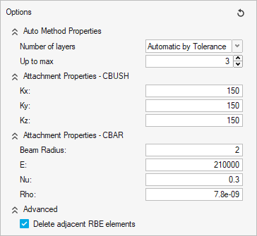
-
Define additional options.
- Auto Method Properties
- Define the number of layers that will be connected in the automatic method.
- Attachment Properties - CBUSH
- Define the CBUSH translational stiffness value for X, Y, and Z
directions for both automatic and manual methods. The property and a
local coordinate system will be automatically created and assigned
to the new CBUSH elements. For the automatic method, the directions
alignment will always be as follows:
Figure 22. 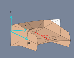
Figure 23. 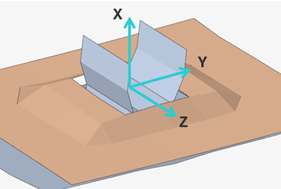
Figure 24. 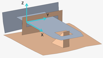
- Attachment Properties - CBAR
- Define the CBAR radius and material properties for both automatic and manual methods. The material, property and beam section will be automatically created and assigned to the created CBAR elements.
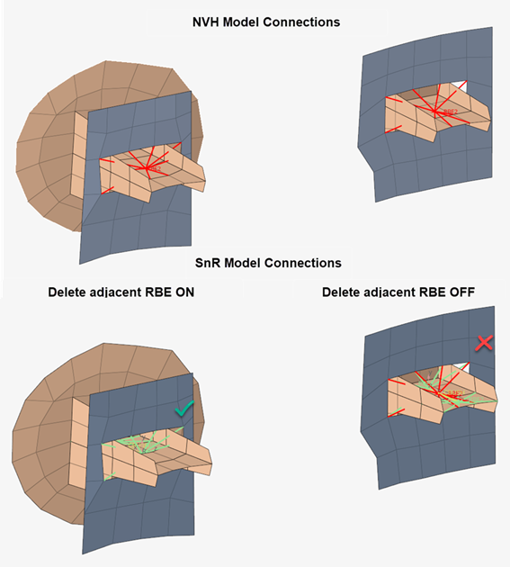
- Advanced - Delete adjacent RBE elements
- The clips and snaps across the NVH model are traditionally modelled
with rigid body elements. Checking this option will automatically
delete any RBE2 element connected to the new RBE2 elements that will
be created by the Create Connections tool. This avoids potential
double dependency errors in the solver.
Figure 25.