
DOE Studies
Once morphing is done, you can create shapes and design variables and submit DOE studies. The DOE study tool can be used for shape and CAD parameter DOEs, and for Automation. The purpose of this tool is to provide automation files so you can manually modify them and carry out DOEs.
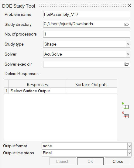
- Problem name
- This is auto-populated from the model file name. If the model is not
saved – save it as an .hm file before using this
tool.Note: The problem name should be same as the name of the hm file saved on disk. The hm file should reside in the Study directory.
- Study directory
- Base directory where all automation files reside. All subsequent DOEs files are in a sub-folder within this directory.
- Solver
- Solver utilized for DOEs or automation run. Based on the selected solver, subsequent fields are changed.
- AcuSolve-specific fields
-
- Solver exec dir
- Path for folder where acuRun.bat is located.
- No of processors
- Run AcuSolve on this many of processors.
- Response definition
- Define variables and surface output.
- Study type
- Select from the list of available studies.
Shapes
Enables DOE studies based on morphed shapes and design variables.
-
Prepare the base model.
- For the AcuSolve solver: Validate geometry, define physics setup, define mesh settings, perform surface meshing, define required surface output.
- For the uFX solver: Generate required surface mesh (no settings required).
- Morph geometry using free morphing tools or morph volumes.
- Create shapes and design variables.
- Open the DOE tool, define relevant fields, then click Launch.
-
Finish setup in HyperStudy.
Note: Do not change variable name/labels in HyperStudy.
For AcuSolve-based DOEs: With each update in design variable, surface mesh is morphed → volume mesh is performed → solver run is submitted → results are extracted.
For uFX-based DOEs: With each shape configuration, surface mesh is morphed → solver run is submitted → post-processing is run in batch.
CAD
Enables DOE studies based on CAD parameters available in the CAD file.
-
Prepare CAD with parameters in CAD system.
CAD parameters defined in NX, Catia, and Inspire are supported for DOE studies.
- You have to setup Define relevant environment to enable CAD system call from HyperMesh CFD.
- For Inspire,you have to define the Inspire path in preferences.
-
Define template for automation.
- For the AcuSolve solver: Define template for geometric operation, boundary conditions, and meshing.
- For the uFX solver: Define template for geometric operation and surface meshing (if required).
- Open the DOE tool, define relevant fields, then click Launch.
-
Finish setup in HyperStudy.
CAD parameters are listed in HyperStudy, activate required CAD parameters.
Note: Do not change variable name/labels in HyperStudy.
For AcuSolve-based DOEs: With each CAD configuration, new CAD is loaded → a template call runs geometric operations, performs setup, volume meshes the model, submits a solver run → results are extracted.
For uFX-based DOEs: With each CAD configuration, new CAD is loaded → a template call runs geometric operations, surface meshing → a solver run is submitted → post-processing is run in batch.
Solver
Enables DOE studies based on parameters defined for solver setup.
-
Prepare the base model.
- For the AcuSolve solver: Validate geometry, define physics setup, define mesh settings, perform surface + volume meshing, define required surface output.
- Create parameters and associate them to physics setup.
- Open the DOE tool, define relevant fields, then click Launch.
-
Finish setup in HyperStudy.
Note: Do not change variable name/labels in HyperStudy.
Mesh
Enables DOE studies based on parameters defined for mesh setup.
-
Prepare the base model.
- For the AcuSolve solver: Validate geometry, define physics setup, define mesh settings, define required surface output.
- Create parameters and associate them to mesh setup.
- Open the DOE tool, define relevant fields, then click Launch.
-
Finish setup in HyperStudy.
Note: Do not change variable name/labels in HyperStudy.
Automation
Enables automation for geometric variant.
- Load a new variant of geometry.
-
Define a template for automation.
- For the AcuSolve solver: Define a template for geometric operations, boundary conditions, and meshing.
- For the uFX solver: Define s template for geometric operations and surface meshing (if required).
-
Open the DOE tool, define relevant fields, then click
Launch.
- In the study directory, open the bat file or shells script, update it as required, and execute that file.