Extractors
Import an .stl file and use it as a sampling surface for variable fields. This surface can be visualized during post-processing and can enable various advanced post-processing. The feature supporting this ability is called an extractor.
Background
Extractors are intended to provide more flexible post-processing and interpolation options by enabling runtime interpolation, access to solid data, moving interpolation surfaces, custom output times and providing variables that are not immediately available through regular field output.
An extractor consists of a set of interpolation points that may follow a solid phase of interest and interpolate different simulation variables at set sampling intervals. Similar to probes and phaseinfo, extractors have access to all simulation data of each phase, solid or fluid, at all times and thus can produce more accurate interpolations, instantaneous or periodically time averaged, compared to those solely relying on field output.
The extractors are defined through a separate parameter section called extractors. Refer to the Command section on this page.
STL File and Output
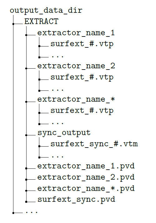
Facet centers will be used as interpolation points. All extractor results are written into the EXTRACT directory under case data directory. Each extractor generates a series of VTK polydata (vtp) files under a directory with the same name as the extractor itself, as well as a pvd file directly under the EXTRACT directory. Extractors may have two types of output:
- Unsynchronized (unsync): the outputs are written according to the internal output interval of the extractor and do not necessarily coincide with the field output write times. The output interval is a constant value. This extractor output may not be suitable for visualization in the same post-processing session as field outputs.
- Synchronized (sync): in addition to unsync outputs, extractor outputs may also be written at field output write times. Field output time internals may be variable or constant. These outputs are suitable for visualization alongside field outputs.
The solver creates a VTK multiblock (vtm) file per filed output time under sync_output directory when sync output is activated for at least one extractor. This vtm file references relevant vtp files of each extractor requesting a sync output. Additionally, a sync_output.pvd file referencing the vtm files is created and placed directly under EXTRACT. The goal is to facilitate the loading of sync output in the same post-processing session as the field data. You may match sync and unsync extractor output times when field output intervals are constant. Figure 1 provides a sample directory structure of the EXTRACT directory. The extractor directory and pvd file names are replaced with the names specified in the cfg file definition of the extractor.
- Both, synchronized and unsynchronized output are affected by start/end time definitions.
- Start/end time can take any values for maximum flexibility. There are no warning messages and sampling and output happen within the defined time interval from start time to end time.
- The end time does not necessarily produce an output if the difference between start time and end time is not a multiple of surface extractor’s output write interval plus one time step size (or zero, depending on how start time coincides with the simulation time).
- The first output and sampling time for a recon run happens at a simulation time larger than the maximum of the start time of the current leg of the run, or defined extractor start time
- Fluid velocity
- Fluid velocity in the direction of surface normal (normal velocity)
- Fluid velocity on the surface (parallel velocity)
- Fluid pressure
- Fluid density
- Kernel volume integral over all resolved phases (Shepard Summation in ParaView with both fluids and solids)
- Kernel volume integral over all fluid phases (Shepard Summation in ParaView with only fluids)
- Sampled particle count over all phases
- Sampled particle count over all fluid phases
- Volume fraction of each fluid phase over all phases
- Volume fraction of each fluid phase over all fluid phases
- Cumulative fluid contact time for each fluid phase
- Cumulative time normalized fluid contact time for each fluid phase
- Periodically time normalized fluid contact time for each fluid phase
- oap - over all phases
- ofp - over fluid phases
- pta - periodically time averaged
Periodically time averaged values do not extend over different legs of a run. For example, time averaging restarts at a new leg of a simulation. Fluid contact time variants of cumulative and cumulative time normalized are based on continuous summation during the current leg of the simulation. They are only reset at the beginning of a new leg of the run. This means at the beginning of a clean or recon run, cumulative and cumulative time normalized fluid contact times start from zero.
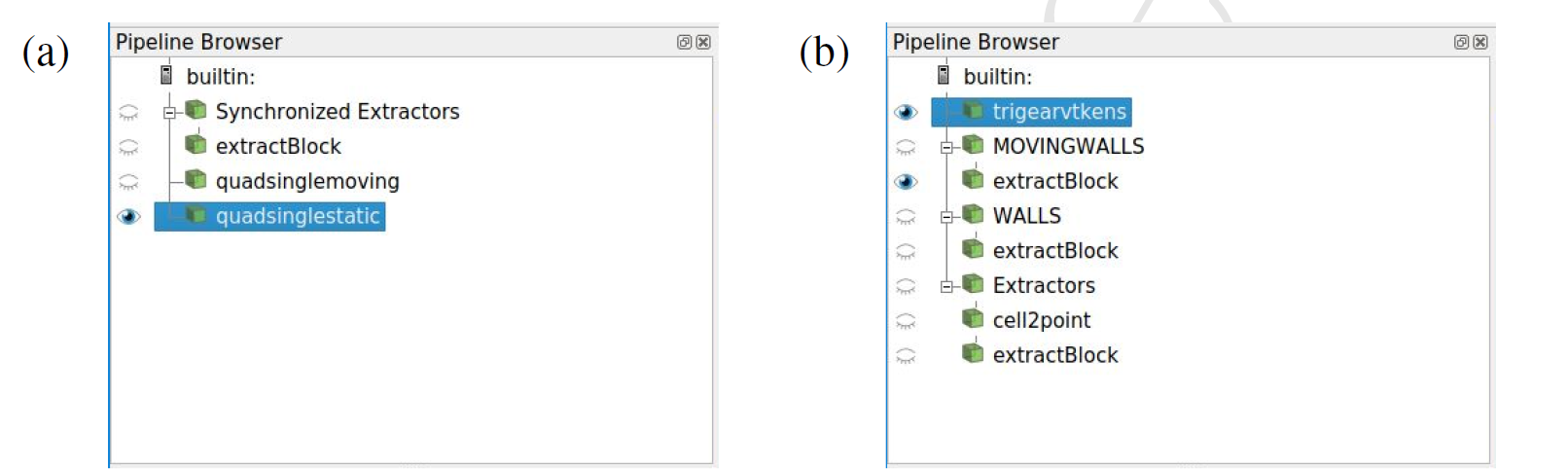
To simplify the loading and viewing process of extractor outputs in ParaView, nanoFluidX writes an additional python state file, extractor.py, under the PVSTATE directory. This state file includes both sync and unsync outputs. Sync output pipeline includes an additional extractBlock (Extract Block) filter to select the visible extractors. Other state files with field data (particles.py from nanoFluidX and PostJobName.py from nanoFluidX[c]) have been updated to include extractor sync output with cell2point (Cell Data to Point Data) and extractBlock filters. When loaded individually in ParaView, the sync output pvd file surfext_sync.pvd will appear as a multiblock data file and an Extract Block filter is required to select an individual extractor or a group of extractors. The extractors write their data on face centers (cell data in VTK/ParaView terminology) and this data is considered to be constant across the cell in ParaView. Using a Cell Data to Point Data filter produces a continuously varying representation. Sample pipelines are shown in Figure 2. The archive created by nFX[c] now includes the EXTRACT directory and extractor.py state file for easier movement of data for post-processing.
Extractors may have a noticeable footprint on simulation time depending on the number of samples and frequency of unsync outputs. It is recommended to use an extractor output time interval larger than phaseinfo output time and shorter than or equal to field output time to balance computational cost and quality of the extractor output. The number of samples depends on the unsync output interval length and the nature of the problem being simulated.
Commands
extractors
{
    extractor
    {
        extractor_name                            surfextname
        extractor_stlfile                         surfext.stl
        extractor_dtoutput                        1.0
        extractor_nsample                         20
        extractor_motphs                          -1
        extractor_syncoutput                      false
        extractor_output_rho_i                    false
        extractor_output_press_i                  false
        extractor_output_vel_i                    false
        extractor_output_velnrm_i                 false
        extractor_output_velpar_i                 false
        extractor_output_kervolint_oap_i          false
        extractor_output_kervolint_ofp_i          false
        extractor_output_prtlcount_oap_i          false
        extractor_output_prtlcount_ofp_i          false
        extractor_output_volfrac_oap_i            false
        extractor_output_volfrac_ofp_i            false
        extractor_output_rho_pta                  true
        extractor_output_press_pta                true
        extractor_output_vel_pta                  true
        extractor_output_velnrm_pta               false
        extractor_output_velpar_pta               false
        extractor_output_kervolint_oap_pta        true
        extractor_output_kervolint_ofp_pta        true
        extractor_output_prtlcount_oap_pta        false
        extractor_output_prtlcount_ofp_pta        false
        extractor_output_volfrac_oap_pta          false
        extractor_output_volfrac_ofp_pta          false
        extractor_output_fct_ptn                  true
        extractor_output_fct_ctn                  true
        extractor_output_fct_c                    true

        extractor_htc_nrpee_bulktemp              273.5
        extractor_output_htc_nrpee_i              false
        extractor_outputtxt_htc_nrpee_i           false
        extractor_output_htc_nrpee_pta            false
        extractor_outputtxt_htc_nrpee_pta         false

        extractor_output_htc_emp_i                false
        extractor_outputtxt_htc_emp_i             false
        extractor_output_htc_emp_pta              false
        extractor_outputtxt_htc_emp_pta           false

        extractor_time_start                      0.0
        extractor_time_end                        1.0
    }
}
Definitions
| Command | Contents | SI Unit Example |
|---|---|---|
| extractor_name | Name of the surface extractor | |
| extractor_stlfile | Name of the .stl file used for defining the interpolation points of surface extractor | |
| extractor_dtoutput | Time interval between non-synchronized outputs, starting from beginning of this run segment | |
| extractor_nsample | Time interval between non-synchronized outputs, starting from
beginning of this run segment Note: This command is
optional. Default = 20 |
|
| extractor_motphs | PhaseID of the MOVINGWALL phase that the
surface extractor is to follow. Note: This command is
optional. Options
Default = -1 |
|
| extractor_syncoutput | Additional extractor output times synchronized with field
data output times Note: This command is optional. Options
Default = true |
|
| extractor_output_rho_i | Set to true to activate instantaneous density
output Note: This command is optional. Options
Default = false |
|
| extractor_output_press_i | Set to true to activate instantaneous pressure
output Note: This command is optional. Options
Default = false |
|
| extractor_output_vel_i | Set to true to activate instantaneous velocity
output Note: This command is optional. Options
Default = false |
|
| extractor_output_velnrm_i | Set to true to activate instantaneous velocity normal to the
surface output Note: This command is optional. Options
Default = false |
|
| extractor_output_kervolint_oap_i | Set to true to activate instantaneous kernel volume integral
over all phases output Note: This command is optional. Options
Default = false |
|
| extractor_output_kervolint_ofp_i | Set to true to activate instantaneous kernel volume integral
over fluid phases output Note: This command is optional. Options
Default = false |
|
| extractor_output_prtlcount_oap_i | Set to true to activate instantaneous sampled particle count
of all phases output Note: This command is optional. Options
Default = false |
|
| extractor_output_prtlcount_ofp_i | Set to true to activate instantaneous sampled particle count
of fluid phases output Note: This command is optional. Options
Default = false |
|
| extractor_output_volfrac_oap_i | Set to true to activate instantaneous volume fraction of
fluid over all phases output Note: This command is
optional. Options
Default = false |
|
| extractor_output_volfrac_ofp_i | Set to true to activate instantaneous volume fraction of
fluid over fluid phases output Note: This command is
optional. Options
Default = false |
|
| extractor_output_rho_pta | Set to true to activate periodically time averaged density
output Note: This command is optional. Options
Default = true |
|
| extractor_output_press_pta | Set to true to activate periodically time averaged pressure
output Note: This command is optional. Options
Default = true |
|
| extractor_output_vel_pta | Set to true to activate periodically time averaged velocity outputSet to true to activate periodically time averaged velocity output | |
| extractor_output_velnrm_pta | Set to true to activate periodically time averaged velocity
normal to the surface output Note: This command is
optional. Options
Default = false |
|
| extractor_output_velpar_pta | Set to true to activate periodically time averaged velocity
parallel to the surface output Note: This command is
optional. Options
Default = false |
|
| extractor_output_kervolint_oap_pta | Set to true to activate periodically time averaged kernel
volume integral over all phases output Note: This command is
optional. Options
Default = true |
|
| extractor_output_kervolint_ofp_pta | Set to true to activate periodically time averaged kernel
volume integral over fluid phases output Note: This command is
optional. Options
Default = true |
|
| extractor_output_prtlcount_oap_pta | Set to true to activate periodically time averaged sampled
particle count of all phases output Note: This command is
optional. Options
Default = true |
|
| extractor_output_prtlcount_ofp_pta | Set to true to activate periodically time averaged sampled
particle count of fluid phases output Note: This command is
optional. Options
Default = false |
|
| extractor_output_volfrac_oap_pta | Set to true to activate periodically time averaged volume
fraction of fluid over all phases output Note: This command is
optional. Options
Default = false |
|
| extractor_output_volfrac_ofp_pta | Set to true to activate periodically time averaged volume
fraction of fluid over fluid phases output Note: This command is
optional. Options
Default = false |
|
| extractor_output_fct_ptn | Set to true to activate periodically time normalized fluid
contact time output Note: This command is optional. Options
Default = true |
|
| extractor_output_fct_ctn | Set to true to activate cumulative time normalized fluid
contact time output Note: This command is optional. Options
Default = true |
|
| extractor_output_fct_c | Set to true to activate cumulative fluid contact time
output Note: This command is optional. Options
Default = true |
|
| extractor_htc_nrpee_bulktemp | Bulk temperature required for calculating nrpee HTC. This
value should be sufficiently different from interpolated wall
temperature to avoid artificially large HTC values. Tip: It is not recommended to use the default
value. Default = 273.5 |
Unit: [K] |
| extractor_output_htc_nrpee_i | Set to true to activate instantaneous nrpee HTC
output Note: This command is optional. Options
Default = false |
|
| extractor_outputtxt_htc_nrpee_i | Set to true to activate instantaneous nrpee HTC output as
space delimited text file Note: This command is optional. Options
Default = false |
|
| extractor_output_htc_nrpee_pta | Set to true to activate periodically time averaged nrpee HTC
output Note: This command is optional. Options
Default = false |
|
| extractor_outputtxt_htc_nrpee_pta | Set to true to activate periodically time averaged nrpee HTC
output as space delimited text file Note: This command is
optional. Options
Default = false |
|
| extractor_output_htc_emp_i | Set to true to activate instantaneous emp HTC
output Note: This command is optional. Options
Default = false |
|
| extractor_outputtxt_htc_emp_i | Set to true to activate instantaneous emp HTC output as space
delimited text file Note: This command is optional. Options
Default = false |
|
| extractor_output_htc_emp_pta | Set to true to activate periodically time averaged emp HTC
output Note: This command is optional. Options
Default = false |
|
| extractor_outputtxt_htc_emp_pta | Set to true to activate periodically time averaged emp HTC
output as space delimited text file Note: This command is
optional. Options
Default = false |
|
| extractor_time_start | Extractor sampling start time Note: This command is
optional. |
Unit: [s] |
| extractor_time_end | Extractor sampling end time Note: This command is
optional. |
Unit: [s] |