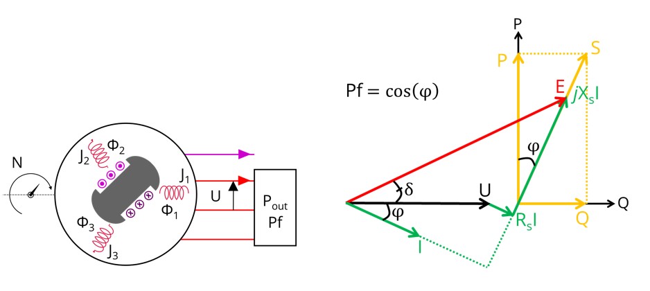
P - Pf - U - N
Positioning and objective
- The output power, which can be either the electrical power transmitted to the stator winding if the machine is in generator operating mode or the mechanical power exerted on the shaft if the machine is in motor operation. If the generator operation is targeted, the output power can be replaced by the apparent power.
- The power factor
- The line-line voltage
- The rotating speed
Through this test, the user can also verify whether the desired operating point is compatible with the machine. Additionally, the user can identify the appropriate reference values for the field current and the control angle needed to achieve this operating point.
The results of this test give an overview of the electromagnetic analysis of the machine, considering its topology.
The general data of the machine, like the machine constant and power balance, are computed and displayed. The user can choose between motor and generator conventions to build the model.
The magnetic flux density is also computed in every region of the machine’s magnetic circuit to evaluate the design.
It also gives the capability to make comparisons between the results obtained from the measurements and those obtained with FluxMotor.
The following table helps to classify the test: “Working point – Sine wave – Motor & Generator – P, Pf, U, N”.
| Family | Working point |
|---|---|
| Package | Sine wave |
| Convention | Motor & Generator |
| Test | P, Pf, U, N |