 Package Modelica.Blocks.Math
Library of Real mathematical functions as input/output blocks
Package Modelica.Blocks.Math
This package contains basic mathematical operations, such as summation and multiplication, and basic mathematical functions, such as sqrt and sin, as input/output blocks. All blocks of this library can be either connected with continuous blocks or with sampled-data blocks.
Extends from Modelica.Icons.Package (Icon for standard packages).
| Name | Description |
|---|---|
Abs | Output the absolute value of the input |
Acos | Output the arc cosine of the input |
Add | Output the sum of the two inputs |
Add3 | Output the sum of the three inputs |
Asin | Output the arc sine of the input |
Atan | Output the arc tangent of the input |
Atan2 | Output atan(u1/u2) of the inputs u1 and u2 |
BooleanChange | Indicates Boolean signal changing |
BooleanToInteger | Convert Boolean to Integer signal |
BooleanToReal | Convert Boolean to Real signal |
ContinuousMean | Calculates the empirical expectation (mean) value of its input signal |
Cos | Output the cosine of the input |
Cosh | Output the hyperbolic cosine of the input |
Division | Output first input divided by second input |
Edge | Indicates rising edge of Boolean signal |
Exp | Output the exponential (base e) of the input |
Feedback | Output difference between commanded and feedback input |
Gain | Output the product of a gain value with the input signal |
Harmonic | Calculate harmonic over period 1/f |
IntegerChange | Indicates integer signal changing |
IntegerToBoolean | Convert Integer to Boolean signal |
IntegerToReal | Convert Integer to Real signals |
InverseBlockConstraints | Construct inverse model by requiring that two inputs and two outputs are identical |
LinearDependency | Output a linear combination of the two inputs |
Log | Output the logarithm (default base e) of the input (input > 0 required) |
Log10 | Output the base 10 logarithm of the input (input > 0 required) |
MatrixGain | Output the product of a gain matrix with the input signal vector |
Max | Pass through the largest signal |
Mean | Calculate mean over period 1/f |
Min | Pass through the smallest signal |
MinMax | Output the minimum and the maximum element of the input vector |
MultiProduct | Product of Reals: y = u[1]*u[2]* ... *u[n] |
MultiSum | Sum of Reals: y = k[1]*u[1] + k[2]*u[2] + ... + k[n]*u[n] |
MultiSwitch | Set Real expression that is associated with the first active input signal |
PolarToRectangular | Convert polar coordinates to rectangular coordinates |
Power | Output the power to a base of the input |
Product | Output product of the two inputs |
Pythagoras | Determine the hypotenuse or leg of a right triangle |
RealFFT | Sampling and FFT of input u |
RealToBoolean | Convert Real to Boolean signal |
RealToInteger | Convert Real to Integer signal |
RectangularToPolar | Convert rectangular coordinates to polar coordinates |
RectifiedMean | Calculate rectified mean over period 1/f |
RootMeanSquare | Calculate root mean square over period 1/f |
Sign | Output the sign of the input |
Sin | Output the sine of the input |
Sinh | Output the hyperbolic sine of the input |
Sqrt | Output the square root of the input (input >= 0 required) |
StandardDeviation | Calculates the empirical standard deviation of its input signal |
Sum | Output the sum of the elements of the input vector |
Tan | Output the tangent of the input |
Tanh | Output the hyperbolic tangent of the input |
TotalHarmonicDistortion | Output the total harmonic distortion (THD) |
UnitConversions … | Conversion blocks to convert between SI and non-SI unit signals |
Variance | Calculates the empirical variance of its input signal |
WrapAngle | Wrap angle to interval ]-pi,pi] or [0,2*pi[ |
 Block Modelica.Blocks.Math.InverseBlockConstraints
Exchange input and output signals of a block, i.e., the previous block inputs become block outputs and the previous block outputs become block inputs. This block is used to construct inverse models. Its usage is demonstrated in example: Modelica.Blocks.Examples.InverseModel.
Note, if a block shall be inverted that has several input and output blocks, then this can be easily achieved by using a vector of InverseBlockConstraints instances:
InverseBlockConstraint invert[3]; // Block to be inverted has 3 input signals
| Type | Name | Description |
|---|---|---|
input RealInput | u1 | Input signal 1 (u1 = u2) |
input RealInput | u2 | Input signal 2 (u1 = u2) |
output RealOutput | y1 | Output signal 1 (y1 = y2) |
output RealOutput | y2 | Output signal 2 (y1 = y2) |
 Block Modelica.Blocks.Math.Gain
This block computes output y as product of gain k with the input u:
y = k * u;
| Type | Name | Default | Description |
|---|---|---|---|
Real | k | Gain value multiplied with input signal |
| Type | Name | Description |
|---|---|---|
input RealInput | u | Input signal connector |
output RealOutput | y | Output signal connector |
 Block Modelica.Blocks.Math.MatrixGain
This blocks computes output vector y as product of the gain matrix K with the input signal vector u:
y = K * u;
Example:
   parameter: K = [0.12 2; 3 1.5]

   results in the following equations:

     | y[1] |     | 0.12  2.00 |   | u[1] |
     |      |  =  |            | * |      |
     | y[2] |     | 3.00  1.50 |   | u[2] |
Extends from Modelica.Blocks.Interfaces.MIMO (Multiple Input Multiple Output continuous control block).
| Type | Name | Default | Description |
|---|---|---|---|
Real | K[:,:] | [1,0; 0,1] | Gain matrix which is multiplied with the input |
final Integer | nin | size(K, 2) | Number of inputs |
final Integer | nout | size(K, 1) | Number of outputs |
| Type | Name | Description |
|---|---|---|
input RealInput | u[nin] | Connector of Real input signals |
output RealOutput | y[nout] | Connector of Real output signals |
 Block Modelica.Blocks.Math.MultiSum
This blocks computes the scalar Real output "y" as sum of the elements of the Real input signal vector u:
y = k[1]*u[1] + k[2]*u[2] + ... k[N]*u[N];
The input connector is a vector of Real input signals. When a connection line is drawn, the dimension of the input vector is enlarged by one and the connection is automatically connected to this new free index (thanks to the connectorSizing annotation).
The usage is demonstrated, e.g., in example Modelica.Blocks.Examples.RealNetwork1.
If no connection to the input connector "u" is present, the output is set to zero: y=0.
Extends from Modelica.Blocks.Interfaces.PartialRealMISO (Partial block with a RealVectorInput and a RealOutput signal).
| Type | Name | Default | Description |
|---|---|---|---|
Integer | significantDigits | 3 | Number of significant digits to be shown in dynamic diagram layer for y |
Integer | nu | 0 | Number of input connections |
Real | k[nu] | fill(1, nu) | Input gains |
| Type | Name | Description |
|---|---|---|
input RealVectorInput | u[nu] | |
output RealOutput | y |
 Block Modelica.Blocks.Math.MultiProduct
This blocks computes the scalar Real output "y" as product of the elements of the Real input signal vector u:
y = u[1]*u[2]* ... *u[N];
The input connector is a vector of Real input signals. When a connection line is drawn, the dimension of the input vector is enlarged by one and the connection is automatically connected to this new free index (thanks to the connectorSizing annotation).
The usage is demonstrated, e.g., in example Modelica.Blocks.Examples.RealNetwork1.
If no connection to the input connector "u" is present, the output is set to zero: y=0.
Extends from Modelica.Blocks.Interfaces.PartialRealMISO (Partial block with a RealVectorInput and a RealOutput signal).
| Type | Name | Default | Description |
|---|---|---|---|
Integer | significantDigits | 3 | Number of significant digits to be shown in dynamic diagram layer for y |
Integer | nu | 0 | Number of input connections |
| Type | Name | Description |
|---|---|---|
input RealVectorInput | u[nu] | |
output RealOutput | y |
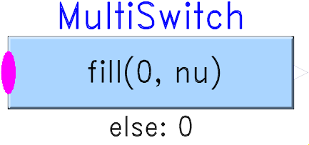 Block Modelica.Blocks.Math.MultiSwitch
This block has a vector of Boolean input signals u[nu] and a vector of (time varying) Real expressions expr[nu]. The output signal y is set to expr[i], if i is the first element in the input vector u that is true. If all input signals are false, y is set to parameter "y_default".
  // Conceptual equation (not valid Modelica)
  i = 'first element of u[:] that is true';
  y = if i==0 then y_default else expr[i];
The input connector is a vector of Boolean input signals. When a connection line is drawn, the dimension of the input vector is enlarged by one and the connection is automatically connected to this new free index (thanks to the connectorSizing annotation).
The usage is demonstrated, e.g., in example Modelica.Blocks.Examples.RealNetwork1.
| Type | Name | Default | Description |
|---|---|---|---|
Real | y_default | 0 | Default value of output y if all u[i] = false |
Integer | nu | 0 | Number of input connections |
Integer | precision | 3 | Number of significant digits to be shown in dynamic diagram layer for y |
| Type | Name | Default | Description |
|---|---|---|---|
Real | expr[nu] | fill(0, nu) | y = if u[i] then expr[i] else y_default (time varying) |
| Type | Name | Description |
|---|---|---|
input BooleanVectorInput | u[nu] | Set y = expr[i], if u[i] = true |
output RealOutput | y | Output depending on expression |
 Block Modelica.Blocks.Math.Sum
This blocks computes output y as sum of the elements of the input signal vector u:
y = u[1] + u[2] + ...;
Example:
     parameter:   nin = 3;

  results in the following equations:

     y = u[1] + u[2] + u[3];
Extends from Modelica.Blocks.Interfaces.MISO (Multiple Input Single Output continuous control block).
| Type | Name | Default | Description |
|---|---|---|---|
Integer | nin | 1 | Number of inputs |
Real | k[nin] | ones(nin) | Optional: sum coefficients |
| Type | Name | Description |
|---|---|---|
input RealInput | u[nin] | Connector of Real input signals |
output RealOutput | y | Connector of Real output signal |
 Block Modelica.Blocks.Math.Feedback
This blocks computes output y as difference of the commanded input u1 and the feedback input u2:
y = u1 - u2;
Example:
     parameter:   n = 2

  results in the following equations:

     y = u1 - u2
| Type | Name | Description |
|---|---|---|
input RealInput | u1 | |
input RealInput | u2 | |
output RealOutput | y |
 Block Modelica.Blocks.Math.Add
This blocks computes output y as sum of the two input signals u1 and u2:
y = k1*u1 + k2*u2;
Example:
     parameter:   k1= +2, k2= -3

  results in the following equations:

     y = 2 * u1 - 3 * u2
Extends from Modelica.Blocks.Interfaces.SI2SO (2 Single Input / 1 Single Output continuous control block).
| Type | Name | Default | Description |
|---|---|---|---|
Real | k1 | 1 | Gain of input signal 1 |
Real | k2 | 1 | Gain of input signal 2 |
| Type | Name | Description |
|---|---|---|
input RealInput | u1 | Connector of Real input signal 1 |
input RealInput | u2 | Connector of Real input signal 2 |
output RealOutput | y | Connector of Real output signal |
 Block Modelica.Blocks.Math.Add3
This blocks computes output y as sum of the three input signals u1, u2 and u3:
y = k1*u1 + k2*u2 + k3*u3;
Example:
     parameter:   k1= +2, k2= -3, k3=1;

  results in the following equations:

     y = 2 * u1 - 3 * u2 + u3;
Extends from Modelica.Blocks.Icons.Block (Basic graphical layout of input/output block).
| Type | Name | Default | Description |
|---|---|---|---|
Real | k1 | 1 | Gain of input signal 1 |
Real | k2 | 1 | Gain of input signal 2 |
Real | k3 | 1 | Gain of input signal 3 |
| Type | Name | Description |
|---|---|---|
input RealInput | u1 | Connector of Real input signal 1 |
input RealInput | u2 | Connector of Real input signal 2 |
input RealInput | u3 | Connector of Real input signal 3 |
output RealOutput | y | Connector of Real output signal |
 Block Modelica.Blocks.Math.Product
This blocks computes the output y as product of the two inputs u1 and u2:
y = u1 * u2;
Extends from Modelica.Blocks.Interfaces.SI2SO (2 Single Input / 1 Single Output continuous control block).
| Type | Name | Description |
|---|---|---|
input RealInput | u1 | Connector of Real input signal 1 |
input RealInput | u2 | Connector of Real input signal 2 |
output RealOutput | y | Connector of Real output signal |
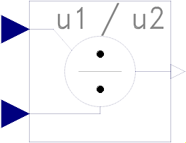 Block Modelica.Blocks.Math.Division
This block computes the output y by dividing the two inputs u1 and u2:
y = u1 / u2;
Extends from Modelica.Blocks.Interfaces.SI2SO (2 Single Input / 1 Single Output continuous control block).
| Type | Name | Description |
|---|---|---|
input RealInput | u1 | Connector of Real input signal 1 |
input RealInput | u2 | Connector of Real input signal 2 |
output RealOutput | y | Connector of Real output signal |
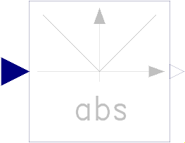 Block Modelica.Blocks.Math.Abs
This blocks computes the output y as absolute value of the input u:
y = abs( u );
The Boolean parameter generateEvent decides whether Events are generated at zero crossing (Modelica specification before 3) or not.
Extends from Modelica.Blocks.Interfaces.SISO (Single Input Single Output continuous control block).
| Type | Name | Default | Description |
|---|---|---|---|
Boolean | generateEvent | false | Choose whether events shall be generated |
| Type | Name | Description |
|---|---|---|
input RealInput | u | Connector of Real input signal |
output RealOutput | y | Connector of Real output signal |
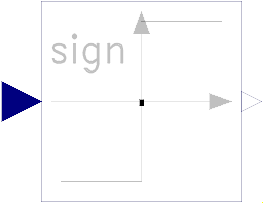 Block Modelica.Blocks.Math.Sign
This blocks computes the output y as sign of the input u:
         1  if u > 0
    y =  0  if u == 0
        -1  if u < 0
The Boolean parameter generateEvent decides whether Events are generated at zero crossing (Modelica specification before 3) or not.
Extends from Modelica.Blocks.Interfaces.SISO (Single Input Single Output continuous control block).
| Type | Name | Default | Description |
|---|---|---|---|
Boolean | generateEvent | false | Choose whether events shall be generated |
| Type | Name | Description |
|---|---|---|
input RealInput | u | Connector of Real input signal |
output RealOutput | y | Connector of Real output signal |
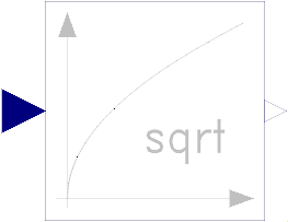 Block Modelica.Blocks.Math.Sqrt
This blocks computes the output y as square root of the input u:
y = sqrt( u );
The input shall be zero or positive. Otherwise an error occurs.
Extends from Modelica.Blocks.Interfaces.SISO (Single Input Single Output continuous control block).
| Type | Name | Description |
|---|---|---|
input RealInput | u | Connector of Real input signal |
output RealOutput | y | Connector of Real output signal |
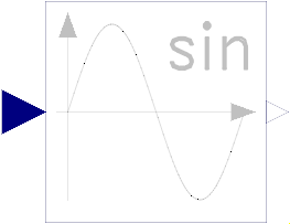 Block Modelica.Blocks.Math.Sin
This blocks computes the output y as sine of the input u:
y = sin( u );
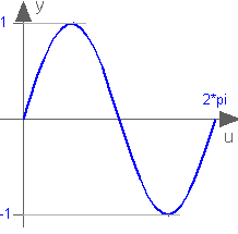
Extends from Modelica.Blocks.Interfaces.SISO (Single Input Single Output continuous control block).
| Type | Name | Description |
|---|---|---|
input RealInput | u | Connector of Real input signal |
output RealOutput | y | Connector of Real output signal |
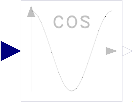 Block Modelica.Blocks.Math.Cos
This blocks computes the output y as cos of the input u:
y = cos( u );
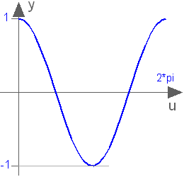
Extends from Modelica.Blocks.Interfaces.SISO (Single Input Single Output continuous control block).
| Type | Name | Description |
|---|---|---|
input RealInput | u | Connector of Real input signal |
output RealOutput | y | Connector of Real output signal |
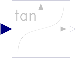 Block Modelica.Blocks.Math.Tan
This blocks computes the output y as tan of the input u:
y = tan( u );
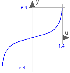
Extends from Modelica.Blocks.Interfaces.SISO (Single Input Single Output continuous control block).
| Type | Name | Description |
|---|---|---|
input RealInput | u | Connector of Real input signal |
output RealOutput | y | Connector of Real output signal |
 Block Modelica.Blocks.Math.Asin
This blocks computes the output y as the sine-inverse of the input u:
y = asin( u );
The absolute value of the input u need to be less or equal to one (abs( u ) <= 1). Otherwise an error occurs.
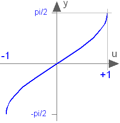
Extends from Modelica.Blocks.Interfaces.SISO (Single Input Single Output continuous control block).
| Type | Name | Description |
|---|---|---|
input RealInput | u | Connector of Real input signal |
output RealOutput | y | Connector of Real output signal |
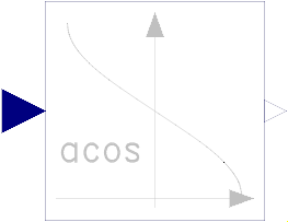 Block Modelica.Blocks.Math.Acos
This blocks computes the output y as the cosine-inverse of the input u:
y = acos( u );
The absolute value of the input u need to be less or equal to one (abs( u ) <= 1). Otherwise an error occurs.
Extends from Modelica.Blocks.Interfaces.SISO (Single Input Single Output continuous control block).
| Type | Name | Description |
|---|---|---|
input RealInput | u | Connector of Real input signal |
output RealOutput | y | Connector of Real output signal |
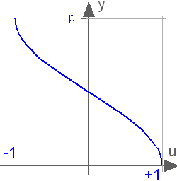
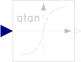 Block Modelica.Blocks.Math.Atan
This blocks computes the output y as the tangent-inverse of the input u:
y= atan( u );
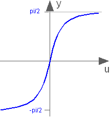
Extends from Modelica.Blocks.Interfaces.SISO (Single Input Single Output continuous control block).
| Type | Name | Description |
|---|---|---|
input RealInput | u | Connector of Real input signal |
output RealOutput | y | Connector of Real output signal |
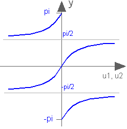
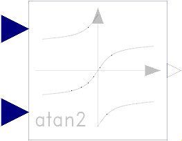 Block Modelica.Blocks.Math.Atan2
This blocks computes the output y as the tangent-inverse of the input u1 divided by input u2:
y = atan2( u1, u2 );
u1 and u2 shall not be zero at the same time instant. Atan2 uses the sign of u1 and u2 in order to construct the solution in the range -180 deg ≤ y ≤ 180 deg, whereas block Atan gives a solution in the range -90 deg ≤ y ≤ 90 deg.
Extends from Modelica.Blocks.Interfaces.SI2SO (2 Single Input / 1 Single Output continuous control block).
| Type | Name | Description |
|---|---|---|
input RealInput | u1 | Connector of Real input signal 1 |
input RealInput | u2 | Connector of Real input signal 2 |
output RealOutput | y | Connector of Real output signal |
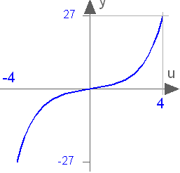
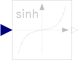 Block Modelica.Blocks.Math.Sinh
This blocks computes the output y as the hyperbolic sine of the input u:
y = sinh( u );
Extends from Modelica.Blocks.Interfaces.SISO (Single Input Single Output continuous control block).
| Type | Name | Description |
|---|---|---|
input RealInput | u | Connector of Real input signal |
output RealOutput | y | Connector of Real output signal |
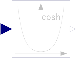 Block Modelica.Blocks.Math.Cosh
This blocks computes the output y as the hyperbolic cosine of the input u:
y = cosh( u );
Extends from Modelica.Blocks.Interfaces.SISO (Single Input Single Output continuous control block).
| Type | Name | Description |
|---|---|---|
input RealInput | u | Connector of Real input signal |
output RealOutput | y | Connector of Real output signal |
 Block Modelica.Blocks.Math.Tanh
This blocks computes the output y as the hyperbolic tangent of the input u:
y = tanh( u );

Extends from Modelica.Blocks.Interfaces.SISO (Single Input Single Output continuous control block).
| Type | Name | Description |
|---|---|---|
input RealInput | u | Connector of Real input signal |
output RealOutput | y | Connector of Real output signal |
 Block Modelica.Blocks.Math.Exp
This blocks computes the output y as the exponential (of base e) of the input u:
y = exp( u );
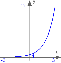
Extends from Modelica.Blocks.Interfaces.SISO (Single Input Single Output continuous control block).
| Type | Name | Description |
|---|---|---|
input RealInput | u | Connector of Real input signal |
output RealOutput | y | Connector of Real output signal |
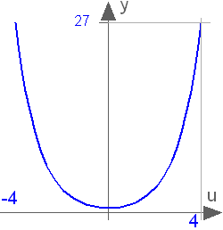
 Block Modelica.Blocks.Math.Power
This blocks computes the output y as the power to the parameter base of the input u. If the boolean parameter useExp is true, the output is determined by:
y = exp ( u * log (base) )
otherwise:
y = base ^ u;
Extends from Modelica.Blocks.Interfaces.SISO (Single Input Single Output continuous control block).
| Type | Name | Default | Description |
|---|---|---|---|
Real | base | Modelica.Constants.e | Base of power |
Boolean | useExp | true | Use exp function in implementation |
| Type | Name | Description |
|---|---|---|
input RealInput | u | Connector of Real input signal |
output RealOutput | y | Connector of Real output signal |
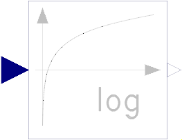 Block Modelica.Blocks.Math.Log
This blocks computes the output y as the logarithm to the parameter base of the input u:
y = log( u ) / log( base );
An error occurs if the input u is zero or negative.
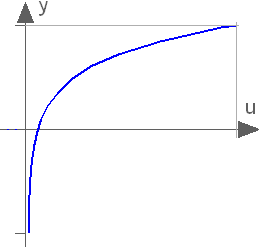
Extends from Modelica.Blocks.Interfaces.SISO (Single Input Single Output continuous control block).
| Type | Name | Default | Description |
|---|---|---|---|
Real | base | Modelica.Constants.e | Base of logarithm |
| Type | Name | Description |
|---|---|---|
input RealInput | u | Connector of Real input signal |
output RealOutput | y | Connector of Real output signal |
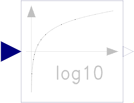 Block Modelica.Blocks.Math.Log10
This blocks computes the output y as the base 10 logarithm of the input u:
y = log10( u );
An error occurs if the input u is zero or negative.
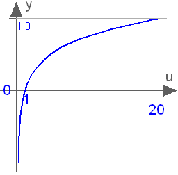
Extends from Modelica.Blocks.Interfaces.SISO (Single Input Single Output continuous control block).
| Type | Name | Description |
|---|---|---|
input RealInput | u | Connector of Real input signal |
output RealOutput | y | Connector of Real output signal |
 Block Modelica.Blocks.Math.WrapAngle
This blocks wraps the input angle into the interval ]-pi,pi], if positiveRange == false.
Otherwise the input angle u is wrapped to the interval [0,2*pi[.
Extends from Modelica.Blocks.Interfaces.SISO (Single Input Single Output continuous control block).
| Type | Name | Default | Description |
|---|---|---|---|
Boolean | positiveRange | false | Use only positive output range, if true |
| Type | Name | Description |
|---|---|---|
input RealInput | u | Connector of Real input signal |
output RealOutput | y | Connector of Real output signal |
 Block Modelica.Blocks.Math.RealToInteger
This block computes the output y as nearest integer value of the input u:
    y = integer( floor( u + 0.5 ) )  for  u > 0;
    y = integer( ceil ( u - 0.5 ) )  for  u < 0;
Extends from Modelica.Blocks.Icons.IntegerBlock (Basic graphical layout of Integer block).
| Type | Name | Description |
|---|---|---|
input RealInput | u | Connector of Real input signal |
output IntegerOutput | y | Connector of Integer output signal |
 Block Modelica.Blocks.Math.IntegerToReal
This block computes the output y as Real equivalent of the Integer input u:
y = u;
where u is of Integer and y of Real type.
Extends from Modelica.Blocks.Icons.Block (Basic graphical layout of input/output block).
| Type | Name | Description |
|---|---|---|
input IntegerInput | u | Connector of Integer input signal |
output RealOutput | y | Connector of Real output signal |
 Block Modelica.Blocks.Math.BooleanToReal
This block computes the output y as Real equivalent of the Boolean input u:
y = if u then realTrue else realFalse;
where u is of Boolean and y of Real type, and realTrue and realFalse are parameters.
Extends from Modelica.Blocks.Interfaces.partialBooleanSI (Partial block with 1 input Boolean signal).
| Type | Name | Default | Description |
|---|---|---|---|
Real | realTrue | 1 | Output signal for true Boolean input |
Real | realFalse | 0 | Output signal for false Boolean input |
| Type | Name | Description |
|---|---|---|
input BooleanInput | u | Connector of Boolean input signal |
output RealOutput | y | Connector of Real output signal |
 Block Modelica.Blocks.Math.BooleanToInteger
This block computes the output y as Integer equivalent of the Boolean input u:
y = if u then integerTrue else integerFalse;
where u is of Boolean and y of Integer type, and integerTrue and integerFalse are parameters.
Extends from Modelica.Blocks.Interfaces.partialBooleanSI (Partial block with 1 input Boolean signal).
| Type | Name | Default | Description |
|---|---|---|---|
Integer | integerTrue | 1 | Output signal for true Boolean input |
Integer | integerFalse | 0 | Output signal for false Boolean input |
| Type | Name | Description |
|---|---|---|
input BooleanInput | u | Connector of Boolean input signal |
output IntegerOutput | y | Connector of Integer output signal |
 Block Modelica.Blocks.Math.RealToBoolean
This block computes the Boolean output y from the Real input u by the equation:
y = u ≥ threshold;
where threshold is a parameter.
Extends from Modelica.Blocks.Interfaces.partialBooleanSO (Partial block with 1 output Boolean signal).
| Type | Name | Default | Description |
|---|---|---|---|
Real | threshold | 0.5 | Output signal y is true, if input u >= threshold |
| Type | Name | Description |
|---|---|---|
input RealInput | u | Connector of Real input signal |
output BooleanOutput | y | Connector of Boolean output signal |
 Block Modelica.Blocks.Math.IntegerToBoolean
This block computes the Boolean output y from the Integer input u by the equation:
y = u ≥ threshold;
where threshold is a parameter.
Extends from Modelica.Blocks.Interfaces.partialBooleanSO (Partial block with 1 output Boolean signal).
| Type | Name | Default | Description |
|---|---|---|---|
Integer | threshold | 1 | Output signal y is true, if input u >= threshold |
| Type | Name | Description |
|---|---|---|
input IntegerInput | u | Connector of Integer input signal |
output BooleanOutput | y | Connector of Boolean output signal |
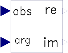
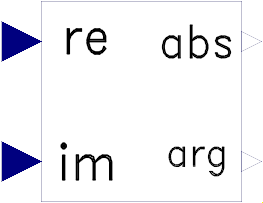 Block Modelica.Blocks.Math.RectangularToPolar
The input values of this block are the rectangular components
u_re and u_im of a phasor in two dimensions.
This block calculates the length y_abs and
the angle y_arg of the polar representation of this phasor.
  y_abs = abs(u_re + j*u_im) = sqrt( u_re2 + u_im2 )
  y_arg = arg(u_re + j*u_im) = atan2(u_im, u_re)
Extends from Modelica.Blocks.Icons.Block (Basic graphical layout of input/output block).
| Type | Name | Description |
|---|---|---|
input RealInput | u_re | Real part of rectangular representation |
input RealInput | u_im | Imaginary part of rectangular representation |
output RealOutput | y_abs | Length of polar representation |
output RealOutput | y_arg | Angle of polar representation |
 Block Modelica.Blocks.Math.PolarToRectangular
The input values of this block are the polar components uabs and uarg of a phasor.
This block calculates the components y_re and y_im of the rectangular representation of this phasor.
   y_re = u_abs * cos( u_arg )
   y_im = u_abs * sin( u_arg )
Extends from Modelica.Blocks.Icons.Block (Basic graphical layout of input/output block).
| Type | Name | Description |
|---|---|---|
input RealInput | u_abs | Length of polar representation |
input RealInput | u_arg | Angle of polar representation |
output RealOutput | y_re | Real part of rectangular representation |
output RealOutput | y_im | Imaginary part of rectangular representation |
 Block Modelica.Blocks.Math.Mean
This block calculates the mean of the input signal u over the given period 1/f:
1 T
- ∫ u(t) dt
T 0
Note: The output is updated after each period defined by 1/f.
If parameter yGreaterOrEqualZero in the Advanced tab is true (default = false), then the modeller provides the information that the mean of the input signal is guaranteed to be ≥ 0 for the exact solution. However, due to inaccuracies in the numerical integration scheme, the output might be slightly negative. If this parameter is set to true, then the output is explicitly set to 0.0, if the mean value results in a negative value.
Extends from Modelica.Blocks.Interfaces.SISO (Single Input Single Output continuous control block).
| Type | Name | Default | Description |
|---|---|---|---|
Frequency | f | Base frequency | |
Real | x0 | 0 | Start value of integrator state |
Boolean | yGreaterOrEqualZero | false | =true, if output y is guaranteed to be >= 0 for the exact solution |
| Type | Name | Description |
|---|---|---|
input RealInput | u | Connector of Real input signal |
output RealOutput | y | Connector of Real output signal |
 Block Modelica.Blocks.Math.RectifiedMean
This block calculates the rectified mean of the input signal u over the given period 1/f, using the mean block.
Note: The output is updated after each period defined by 1/f.
Extends from Modelica.Blocks.Interfaces.SISO (Single Input Single Output continuous control block).
| Type | Name | Default | Description |
|---|---|---|---|
Frequency | f | Base frequency | |
Real | x0 | 0 | Start value of integrator state |
| Type | Name | Description |
|---|---|---|
input RealInput | u | Connector of Real input signal |
output RealOutput | y | Connector of Real output signal |
 Block Modelica.Blocks.Math.ContinuousMean
This block continuously calculates the mean value of its input signal. It uses the function:
    integral( u over time)
y = ----------------------
      time - startTime
This can be used to determine the empirical expectation value of a random signal, such as generated by the Noise blocks.
The parameter t_eps is used to guard against division by zero (the mean value computation starts at <simulation start time> + t_eps and before that time instant y = u).
See also the Mean block for a sampled implementation.
This block is demonstrated in the examples UniformNoiseProperties and NormalNoiseProperties.
Extends from Modelica.Blocks.Icons.Block (Basic graphical layout of input/output block).
| Type | Name | Default | Description |
|---|---|---|---|
Time | t_eps | 1e-7 | Mean value calculation starts at startTime + t_eps |
| Type | Name | Description |
|---|---|---|
input RealInput | u | Noisy input signal |
output RealOutput | y | Expectation (mean) value of the input signal |
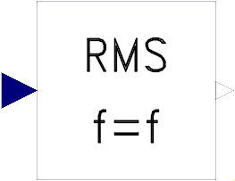 Block Modelica.Blocks.Math.RootMeanSquare
This block calculates the root mean square of the input signal u over the given period 1/f, using the mean block.
Note: The output is updated after each period defined by 1/f.
Extends from Modelica.Blocks.Interfaces.SISO (Single Input Single Output continuous control block).
| Type | Name | Default | Description |
|---|---|---|---|
Frequency | f | Base frequency | |
Real | x0 | 0 | Start value of integrator state |
| Type | Name | Description |
|---|---|---|
input RealInput | u | Connector of Real input signal |
output RealOutput | y | Connector of Real output signal |
 Block Modelica.Blocks.Math.Variance
This block calculates the empirical variance of its input signal. It is based on the formula (but implemented in a more reliable numerical way):
y = mean( (u - mean(u))^2 )
The parameter t_eps is used to guard against division by zero (the variance computation starts at <simulation start time> + t_eps and before that time instant y = 0).
The variance of a signal is also equal to its mean power.
This block is demonstrated in the examples UniformNoiseProperties and NormalNoiseProperties.
Extends from Modelica.Blocks.Icons.Block (Basic graphical layout of input/output block).
| Type | Name | Default | Description |
|---|---|---|---|
Time | t_eps | 1e-7 | Variance calculation starts at startTime + t_eps |
| Type | Name | Description |
|---|---|---|
input RealInput | u | Noisy input signal |
output RealOutput | y | Variance of the input signal |
 Block Modelica.Blocks.Math.StandardDeviation
This block calculates the standard deviation of its input signal. The standard deviation is the square root of the signal's variance:
y = sqrt( variance(u) )
The Variance block is used to calculate variance(u).
The parameter t_eps is used to guard against division by zero (the computation of the standard deviation starts at <simulation start time> + t_eps and before that time instant y = 0).
This block is demonstrated in the examples UniformNoiseProperties and NormalNoiseProperties.
Extends from Modelica.Blocks.Icons.Block (Basic graphical layout of input/output block).
| Type | Name | Default | Description |
|---|---|---|---|
Time | t_eps | 1e-7 | Standard deviation calculation starts at startTime + t_eps |
| Type | Name | Description |
|---|---|---|
input RealInput | u | Noisy input signal |
output RealOutput | y | Standard deviation of the input signal |
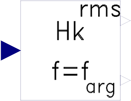 Block Modelica.Blocks.Math.Harmonic
This block calculates the root mean square and the phase angle of a single harmonic k of the input signal u over the given period 1/f, using the mean block.
Note: The output is updated after each period defined by 1/f.
Note:
The harmonic is defined by √2 rms cos(k 2 π f t - arg) if useConjugateComplex=false (default)
The harmonic is defined by √2 rms cos(k 2 π f t + arg) if useConjugateComplex=true
Extends from Modelica.Blocks.Icons.Block (Basic graphical layout of input/output block).
| Type | Name | Default | Description |
|---|---|---|---|
Frequency | f | Base frequency | |
Integer | k | Order of harmonic | |
Boolean | useConjugateComplex | false | Gives conjugate complex result if true |
Real | x0Cos | 0 | Start value of cos integrator state |
Real | x0Sin | 0 | Start value of sin integrator state |
| Type | Name | Description |
|---|---|---|
input RealInput | u | |
output RealOutput | y_rms | Root mean square of polar representation |
output RealOutput | y_arg | Angle of polar representation |
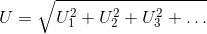
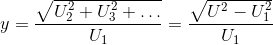
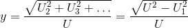
 Block Modelica.Blocks.Math.TotalHarmonicDistortion
This block determines the total harmonic distortion (THD) over the given period 1/f.
Consider that the input u consists of harmonic RMS components
U1, U2, U3, etc.
The total RMS component is then determined by:
The calculation of the total harmonic distortion is based on the parameter useFirstHarmonic.
The default value useFirstHarmonic = true represents the standard THD calculation used in
electrical engineering.
The non-default value useFirstHarmonic = false
calculates the THD typically used for the assessment of audio signals.
If useFirstHarmonic = true, the total higher harmonic content (harmonic order numbers > 1)
refers to the RMS value of the fundamental wave:
If useFirstHarmonic = false, the total higher harmonic content (harmonic order numbers > 1)
refers to the total RMS:
In case of a zero input signal or within the first period of calculation, the boolean output signal
valid becomes false to indicate that the calculation result is not valid. Valid
calculations are indicated by valid = true.
Extends from Modelica.Blocks.Interfaces.SISO (Single Input Single Output continuous control block).
| Type | Name | Default | Description |
|---|---|---|---|
Frequency | f | Base frequency | |
Boolean | useFirstHarmonic | true | THD with respect to first harmonic, if true; otherwise with respect to total RMS |
| Type | Name | Description |
|---|---|---|
input RealInput | u | Connector of Real input signal |
output RealOutput | y | Connector of Real output signal |
output BooleanOutput | valid | True, if output y is valid |
 Block Modelica.Blocks.Math.RealFFT
This block samples the input signal, calculates the Fast Fourier Transform by function Math.realFFT, and (when simulation terminates) writes the output to result file resultFileName by function Math.realFFTwriteToFile.
The number of sampling points as well as the samplePeriod is calculated from desired maximum frequency f_max and frequency resolution f_res.
The user has to take care that enough points can be sampled before the simulation ends: startTime + (ns - 1)*samplePeriod <= stopTime.
The result file is written as mat, first column = frequency, second column = amplitudes, third column = phases. The frequency points are separated by rows with amplitude and phase = 0, so one can plot the result directly as frequency lines.
Extends from Modelica.Blocks.Interfaces.DiscreteBlock (Base class of discrete control blocks).
| Type | Name | Default | Description |
|---|---|---|---|
final Time | samplePeriod | (2 * f_res * div(ns, 2)) ^ (-1) | Sample period of component |
Time | startTime | 0 | First sample time instant |
Frequency | f_max | Maximum frequency of interest | |
Frequency | f_res | Frequency resolution | |
final Integer | ns | Modelica.Math.FastFourierTransform.realFFTsamplePoints(f_max, f_res, f_max_factor = 5) | Number of samples |
final Integer | nf | max(1, min(integer(ceil(f_max / f_res)) + 1, div(ns, 2))) | Number of frequency points |
String | resultFileName | "realFFT.mat" | Result file: f, abs, arg |
| Type | Name | Description |
|---|---|---|
input RealInput | u |
 Block Modelica.Blocks.Math.Pythagoras
This block determines the hypotenuse y = sqrt(u1^2 + u2^2)
if the boolean parameter u1IsHyotenuse = false.
In this case the two inputs u1 and
u2 are interpreted as the legs of a right triangle
and the boolean output valid is always equal to
true.
If u1IsHyotenuse = true, input u1 is interpreted as hypotenuse and u2
is one of the two legs of a right triangle.
Then, the other of the two legs of the right triangle is the output, determined by
y = sqrt(u1^2 - u2^2), if u1^2 - u2^2 ≥ 0; in this case the
boolean output valid is equal to true. In case of u1^2 - u2^2 < 0, the
output y = 0 and valid is set to false.
Extends from Modelica.Blocks.Interfaces.SI2SO (2 Single Input / 1 Single Output continuous control block).
| Type | Name | Default | Description |
|---|---|---|---|
Boolean | u1IsHypotenuse | false | = true, if u1 is the hypotenuse and y is one leg |
| Type | Name | Description |
|---|---|---|
input RealInput | u1 | Connector of Real input signal 1 |
input RealInput | u2 | Connector of Real input signal 2 |
output RealOutput | y | Connector of Real output signal |
output BooleanOutput | valid | = true, if y is a valid result |
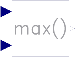 Block Modelica.Blocks.Math.Max
This block computes the output y as maximum of the two Real inputs u1 and u2:
y = max ( u1 , u2 );
Extends from Modelica.Blocks.Interfaces.SI2SO (2 Single Input / 1 Single Output continuous control block).
| Type | Name | Description |
|---|---|---|
input RealInput | u1 | Connector of Real input signal 1 |
input RealInput | u2 | Connector of Real input signal 2 |
output RealOutput | y | Connector of Real output signal |
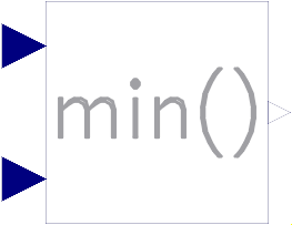 Block Modelica.Blocks.Math.Min
This block computes the output y as minimum of the two Real inputs u1 and u2:
y = min ( u1 , u2 );
Extends from Modelica.Blocks.Interfaces.SI2SO (2 Single Input / 1 Single Output continuous control block).
| Type | Name | Description |
|---|---|---|
input RealInput | u1 | Connector of Real input signal 1 |
input RealInput | u2 | Connector of Real input signal 2 |
output RealOutput | y | Connector of Real output signal |
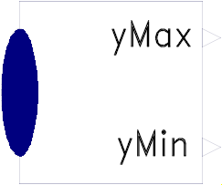 Block Modelica.Blocks.Math.MinMax
Determines the minimum and maximum element of the input vector and provide both values as output.
Extends from Modelica.Blocks.Icons.Block (Basic graphical layout of input/output block).
| Type | Name | Default | Description |
|---|---|---|---|
Integer | nu | 0 | Number of input connections |
| Type | Name | Description |
|---|---|---|
input RealVectorInput | u[nu] | |
output RealOutput | yMax | |
output RealOutput | yMin |
 Block Modelica.Blocks.Math.LinearDependency
Determine the linear combination of the two inputs: y = y0*(1 + k1*u1 + k2*u2)
Note, for y0=0 the output is always zero.
To improve the implementation, the formula will be changed (non-backwards compatible) in the future: y = y0 + k1*u1 + k2*u2
Extends from Modelica.Blocks.Interfaces.SI2SO (2 Single Input / 1 Single Output continuous control block).
| Type | Name | Default | Description |
|---|---|---|---|
Real | y0 | 0 | Initial value |
Real | k1 | 0 | u1 dependency |
Real | k2 | 0 | u2 dependency |
| Type | Name | Description |
|---|---|---|
input RealInput | u1 | Connector of Real input signal 1 |
input RealInput | u2 | Connector of Real input signal 2 |
output RealOutput | y | Connector of Real output signal |
 Block Modelica.Blocks.Math.Edge
This block sets the Boolean output y to true, when the Boolean input u shows a rising edge:
y = edge( u );
Extends from Modelica.Blocks.Interfaces.BooleanSISO (Single Input Single Output control block with signals of type Boolean).
| Type | Name | Description |
|---|---|---|
input BooleanInput | u | Connector of Boolean input signal |
output BooleanOutput | y | Connector of Boolean output signal |
 Block Modelica.Blocks.Math.BooleanChange
This block sets the Boolean output y to true, when the Boolean input u shows a rising or falling edge, i.e., when the signal changes:
y = change( u );
Extends from Modelica.Blocks.Interfaces.BooleanSISO (Single Input Single Output control block with signals of type Boolean).
| Type | Name | Description |
|---|---|---|
input BooleanInput | u | Connector of Boolean input signal |
output BooleanOutput | y | Connector of Boolean output signal |
 Block Modelica.Blocks.Math.IntegerChange
This block sets the Boolean output y to true, when the Integer input u changes:
y = change( u );
Extends from Modelica.Blocks.Interfaces.IntegerSIBooleanSO (Integer Input Boolean Output continuous control block).
| Type | Name | Description |
|---|---|---|
input IntegerInput | u | Connector of Integer input signal |
output BooleanOutput | y | Connector of Boolean output signal |