The transient stress test item uses the SPICE Engine, it makes a SPICE net list,
finds the node voltage, and checks whether all passive components connected to the net are
within the allowable voltage range.
Figure 1.
Power Net:
Select power net group to which passive components are connected.
Ground Net:
Select ground net group to which passive components are connected.
Start Component:
Select start component of power net. Normally Power Device or Connector can
be a start component of power net.
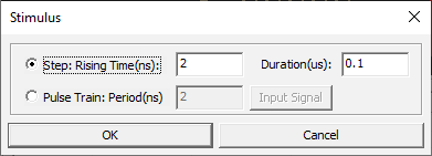
Stimulus: Set
input stimulus of SPICE net list. You can assign Step Pulse or Pulse
Train.Figure 2.
Voh: Set the
output high voltage (Voh) of driver pin. You can set this by entering the
value directly or select the property name which contain voh value.
Vol: Set the
output low voltage (Vol) of driver pin. You can set this by entering the
value directly or select the property name which contain vol value.
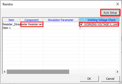
Set Resistor
Set resistor component parameters for the Transient Stress Test item.
Double-click the empty field in the Resistor column to open the
Resistor dialog.
Figure 3.
If this stress test-item was previously
set, click Auto Setup to import all properties except for
Simulation Parameter and Simulation Model.
Note:If the stress test-item was not
set, refer to Resistor for
setup.
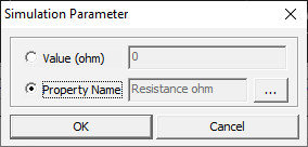
Double-click the empty field in the
Simulation Parameter column, and then select from the following:
To enter the value of resistance, select Value
(ohm).
To select the property that contains the value of resistance, select
Property Name.
Figure 4.
Optional: To register a SPICE model, double-click
the empty field, and then use the File Explorer to select the
.model file.
Click OK to exit
the dialog.
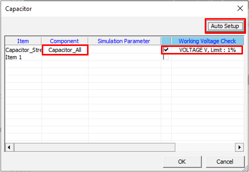
Set Capacitor
Set capacitor component parameters for the Transient Stress Test item.
Double-click the empty field in the Capacitor column to open the
dialog.
Figure 5.
If this stress test-item was previously
set, click Auto Setup to import all properties except for
Simulation Parameter and Simulation Model.
Note:If the stress test-item was not
set, refer to Capacitor for
setup.
Double-click the empty field in the
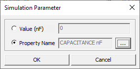
Simulation Parameter column, and then select from the following:
To enter the value of capacitance, select Value
(ohm).
To select the property that contains the value of capacitance, select
Property Name.
Figure 6.
Optional: To register a SPICE model, double-click
the empty field, and then use the File Explorer to select the
.model file.
Click OK to exit
the dialog.
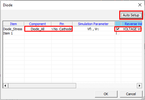
Set Diode
Set diode component parameters for the Transient Stress Test item.
Double-click the empty field in the Diode column to open the
Diode dialog.
Figure 7.
If this stress test-item was previously
set, click Auto Setup to import all properties except for
Simulation Parameter and Simulation Model.
Note:If the stress test-item was not
set, refer to Diode for
setup.
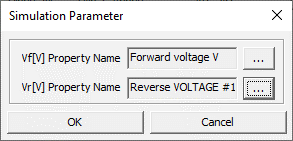
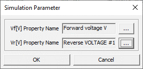
Double-click the empty field in the
Simulation Parameter column, and then do the following:
Select the property that contains the forward voltage.
Select the property that contains the reverse voltage.
Figure 8.
Optional: To register a SPICE model, double-click
the empty field, and then use the File Explorer to select the
.model file.
Click OK to exit
the dialog.
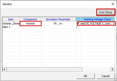
Set Varistor
Set varistor component parameters for the Transient Stress Test item.
Double-click the empty field in the Varistor column to open the
Varistor dialog.
Figure 9.
If this stress test-item was previously
set, click Auto Setup to import all properties except for
Simulation Parameter and Simulation Model.
Note:If the stress test-item was not
set, refer to Varistor for
setup.
Double-click the empty field in the
Simulation Parameter column, and then do the following:
Select the property that contains the forward voltage.
Select the property that contains the reverse voltage.
Figure 10.
Optional: To register a SPICE model, double-click
the empty field, and then use the File Explorer to select the
.model file.
Click OK to exit
the dialog.
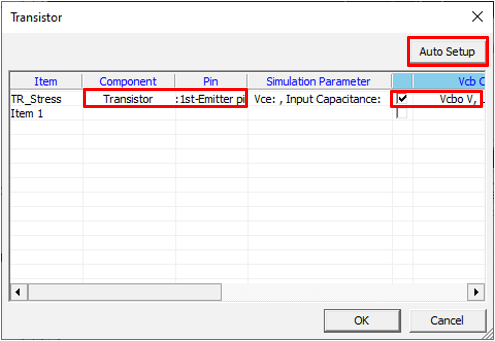
Set Transistor
Set transistor component parameters for the Transient Stress Test item.
Double-click the empty field in the Transistor column to open the
Transistor dialog.
Figure 11.
If this stress test-item was previously
set, click Auto Setup to import all properties except for
Simulation Parameter and Simulation Model.
Note:If the stress test-item was not
set, refer to Transistor for
setup.
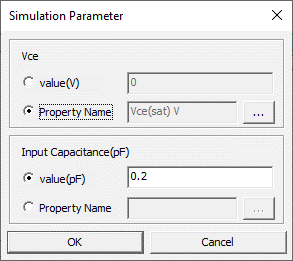
Double-click the empty field in the
Simulation Parameter column, and then do the following:
For Vce, enter the value or select the
property.
For Input Capacitance(pF), enter the value or
select the property.
Figure 12.
Optional: To register a SPICE model, double-click
the empty field, and then use the File Explorer to select the
.model file.
Click OK to exit
the dialog.
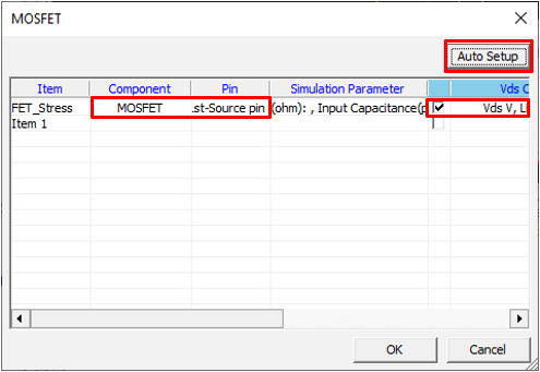
Set MOFSET
Set MOFSET component parameters for the Transient Stress Test item.
Double-click the empty field in the MOFSET column to open the
MOFSET dialog.
Figure 13.
If this stress test-item was previously
set, click Auto Setup to import all properties except for
Simulation Parameter and Simulation Model.
Note:If the stress test-item was not
set, refer to MOSFET for
setup.
Double-click the empty field in the
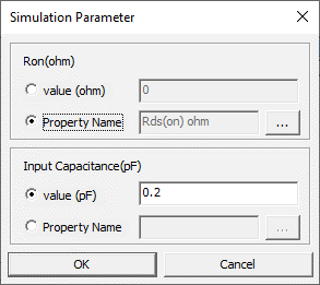
Simulation Parameter column, and then do the following:
For Ron, enter the value or select the
property.
For Input Capacitance(pF), enter the value or
select the property.
Figure 14.
Optional: To register a SPICE model, double-click
the empty field, and then use the File Explorer to select the
.model file.
Click OK to exit
the dialog.
Set Photo Coupler
Set Photo Coupler component parameters for the Transient Stress Test
item.
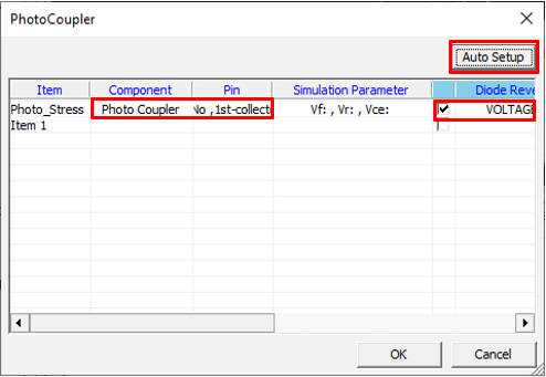
Double-click the empty field in the Photo Coupler column to open the
Photo Coupler dialog.
Figure 15.
If this stress test-item was previously
set, click Auto Setup to import all properties except for
Simulation Parameter and Simulation Model.
Note:If the stress test-item was not
set, refer to Photo Coupler
for setup.
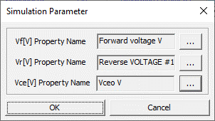
Double-click the empty field in the
Simulation Parameter column, and then do the following:
Select the property that contains the forward voltage.
Select the property that contains the reverse voltage.
Select the property that contains the Vceo voltage.
Figure 16.
Optional: To register a SPICE model, double-click
the empty field, and then use the File Explorer to select the
.model file.
Click OK to exit
the dialog.
Set Linear Regulator
Set linear regulator component parameters for the Transient Stress Test
item.
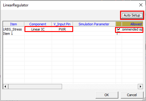
Double-click the empty field in the Linear Regulator column to open the
Linear Regulator dialog.
Figure 17.
If this stress test-item was previously
set, click Auto Setup to import all properties except for
Simulation Parameter and Simulation Model.
Note:If the stress test-item was not
set, refer to Linear Regulator for setup.
Double-click the empty field in the
Simulation Parameter column, and then select from the following:
To enter the value of input capacitance, select Value
(pF).
To select the property that contains the value of input capacitance,
seleFigure 18. ct Property Name.
Optional: To register a SPICE model, double-click
the empty field, and then use the File Explorer to select the
.model file.
Click OK to exit
the dialog.
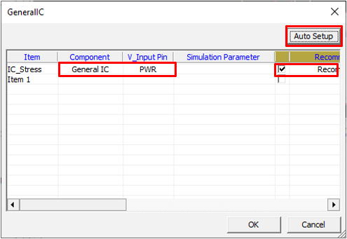
Set General IC
Set General IC component parameters for the Transient Stress Test item.
Double-click the empty field in the General IC column to open the
General IC dialog.
Figure 19.
If this stress test-item was previously
set, click Auto Setup to import all properties except for
Simulation Parameter and Simulation Model.
Note:If the stress test-item was not
set, refer to General IC for
setup.
Double-click the empty field in the
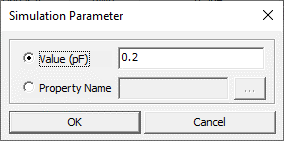
Simulation Parameter column, and then select from the following:
To enter the value of input capacitance, select Value
(pF).
To select the property that contains the value of input capacitance,
Figure 20. select Property Name.
Optional: To register a SPICE model, double-click
the empty field, and then use the File Explorer to select the
.model file.
Click OK to exit
the dialog.
Set Fuse
Set fuse component parameters for the Transient Stress Test item.
Double-click the empty field in the Fuse column to open the
Fuse dialog.
Figure 21.
If this stress test-item was previously
set, click Auto Setup to import all properties except for
Simulation Parameter and Simulation Model.
Note:If the stress test-item was not
set, refer to Fuse for
setup.
Double-click the empty field in the
Simulation Parameter column, and then select from the following:
To enter the value of resistance (RON), select Value
(ohm).
To select the property that contains the value of resistance (RON),
select Property Name.
Figure 22.
Optional: To register a SPICE model, double-click
the empty field, and then use the File Explorer to select the
.model file.
Click OK to exit
the dialog.
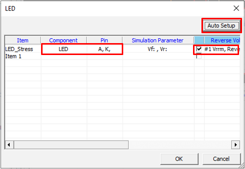
Set LED
Set LED component parameters for the Transient Stress Test item.
Double-click the empty field in the LED column to open the
LED dialog.
Figure 23.
If this stress test-item was previously
set, click Auto Setup to import all properties except for
Simulation Parameter and Simulation Model.
Note:If the stress test-item was not
set, refer to LED for
setup.
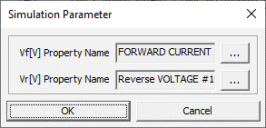
Double-click the empty field in the
Simulation Parameter column, and then do the following:
Select the property that contains the forward voltage.
Select the property that contains the reverse voltage.
Figure 24.
Optional: To register a SPICE model, double-click
the empty field, and then use the File Explorer to select the
.model file.
Click OK to exit
the dialog.
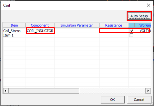
Set Coil
Set coil component parameters for the Transient Stress Test item.
Double-click the empty field in the Coil column to open the
Coil dialog.
Figure 25.
If this stress test-item was previously
set, click Auto Setup to import all properties except for
Simulation Parameter and Simulation Model.
Note:If the stress test-item was not
set, refer to Coil for
setup.
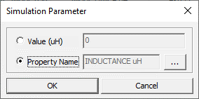
Double-click the empty field in the
Simulation Parameter column, and then select from the following:
To enter the value of inductance, select Value
(uH).
To select the property that contains the value of inductance, select
Property Name.
Figure 26.
Optional: To register a SPICE model, double-click
the empty field, and then use the File Explorer to select the
.model file.
Click OK to exit
the dialog.
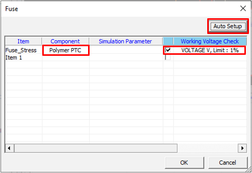
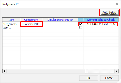
Set Polymer PTC
Set Polymer PTC component parameters for the Transient Stress Test item.
Double-click the empty field in the Polymer PTC column to open the
Polymer PTC dialog.
Figure 27.
If this stress test-item was previously
set, click Auto Setup to import all properties except for
Simulation Parameter and Simulation Model.
Note:If the stress test-item was not
set, refer to Polymer PTC
for setup.
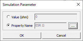
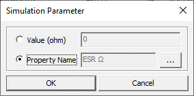
Double-click the empty field in the
Simulation Parameter column, and then select from the following:
To enter the value of resistance (ESR), select Value
(ohm).
To select the property that contains the value of resistance (ESR),
select Property Name.
Figure 28.
Optional: To register a SPICE model, double-click
the empty field, and then use the File Explorer to select the
.model file.
Click OK to exit
the dialog.
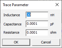
Set Trace Parameter
Set trace parameters for the Transient Stress Test item.
Circuit level simulation does not reflect trace parasitic. You can assign a trace
parasitic value (R, L, C).
Double-click the empty field in the Trace Parameter column to open the
Trace Parameter dialog.
Figure 29.
Double-click the empty field in the
Simulation Parameter column, and then do the following: