Supported Elements
Supported elements for topology composition.
- Receiver Pin: Can add any numbers of receiver pin model to the selected
topology. And can assign Part Name and Pin Name by clicking
 menu below. Click the desired Part and Pin
names and click OK in the Select
Part/Pin dialog.
menu below. Click the desired Part and Pin
names and click OK in the Select
Part/Pin dialog.Figure 2. 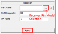
- Single Line: Can select and use the single line model which already saved
using the Analysis > Transmission Line Analysis feature. Select the desired
single trace model and define the length for it.
Figure 3. 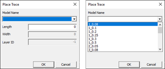
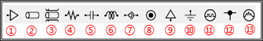
- Coupled Line: Can select and use the coupled line model which already saved using the Analysis > Transmission Line Analysis feature. Single line models are not listed up here, the lines coupled with more than two listed for selection at ① below.
- Resistor: Can select and use a resistor model from the resistor parts.
- Capacitor: Can select and use a capacitor model from the capacitor parts.
- Inductor: Can select and use an inductor model from the inductor parts.
- Connector: S parameter/SPICE model can be used for connector parts.
- Via: Can select and use a via model among available via parts included in the activated PCB system.
- DC Source: Can apply a DC voltage at a certain node.
- GND: Can apply ground voltage at a certain node.
- Probe: Can add any numbers of voltage probe at certain internal nodes of the topology.
- Merged Node: The nodes having the same name of this will be treated as connected.
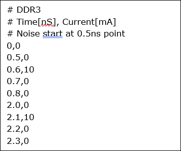
- External Noise: You can apply the external current noise waveform to any
point on the topology by using this menu. Upon clicking this icon, the
Place Noise Input dialog will be open, you can
assign current noise waveform file using this menu.
- Noise Name: Noise input node name. You can change the name.
- Time Unit: Time unit of noise input file.
- Current Unit: Current unit of noise input file.
- Delay Time: You can add insert delay for noise input.
- File Name: Assign current noise input file. Supported noise input
file formats are .csv and .dat file formats. See Sample
.csv file below.
Figure 4.