Net properties are basic attributes influencing the electrical analysis.
Manage Net Properties :
Power/Ground Nets: The voltage assigned to a Power or Ground net will
automatically be applied as the termination voltage to any connected
terminator pins.
Differential Pairs: For nets defined as Differential Signal Positive
(+) and Negative (-), you only need to assign the driver model to either the
Positive (+) or Negative (-) net. PollEx will automatically recognize and
simulate the pair as a differential signal if the differential Pair Net
string set properly.
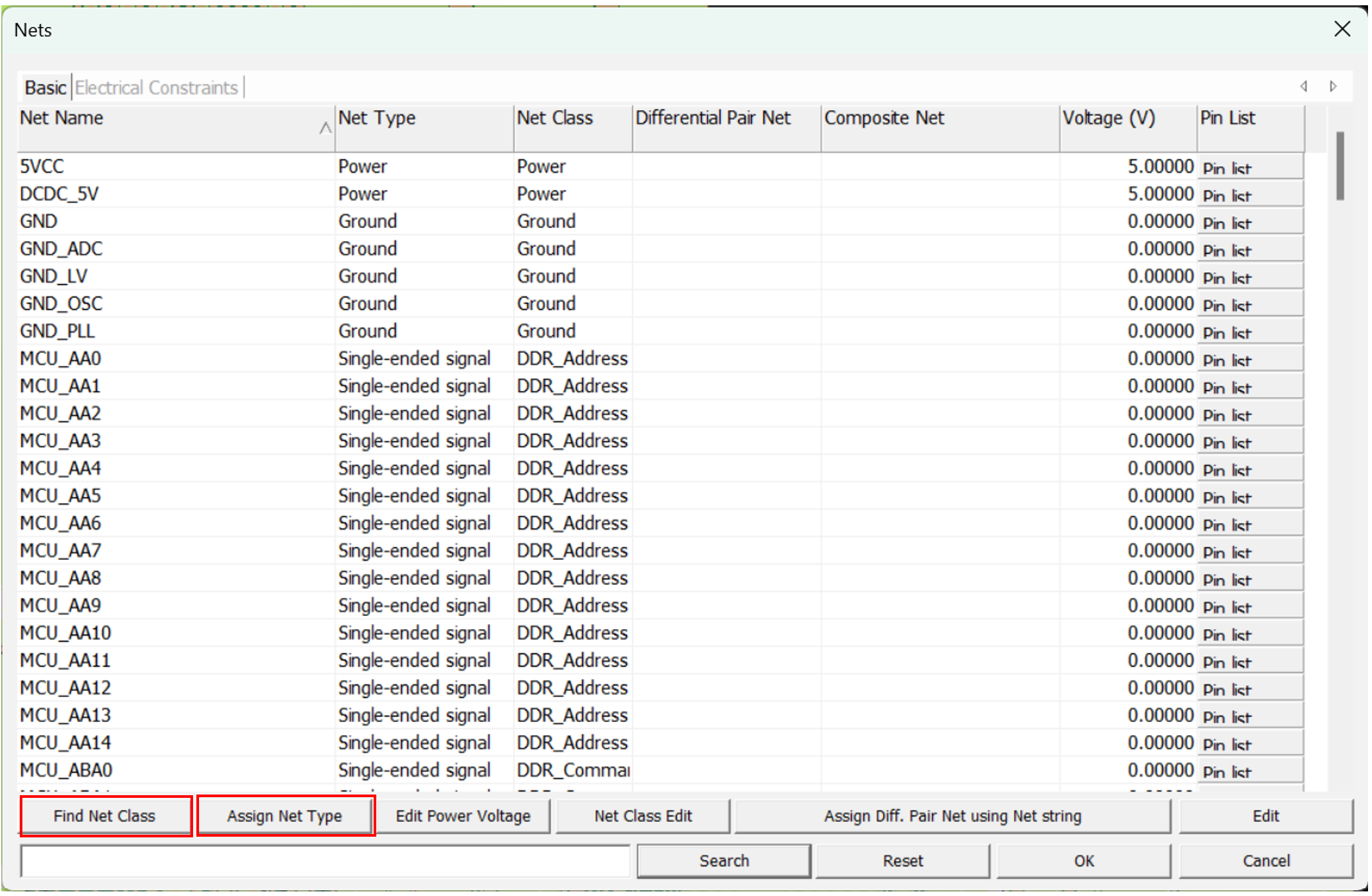
Editing Net Properties:
Open the Properties > Nets menu to access a dialog with
default settings for all nets in the active PCB system.
To customize a net, double-click on it or select it and click
Edit. You can then define or modify the Net Type,
Voltage, and electrical constraints.
Pin List: Click Pin List to view all the pins connected to the
selected net.
By clicking Assign Net Type, you can set net property
automatically using net information described in IBIS files and property.
By clicking Find Net Class, you can set net class
automatically using pre-defined net class search string file.
Figure 1.
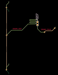
Composite Nets
When two or more nets are serially connected through passive components such as
resistor, electrical analysis must be made for the entire signal path encompassing the
multiple nets connected with these passive components.
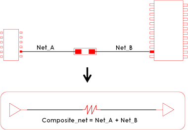
These
nets are modeled as composite nets in PollEx PCB
environment. The composite nets are automatically generated by PollEx PCB which references the schematic data to configure it
by checking the connectivity of the selected passive components to each
net.
Figure 2.
Figure 3.
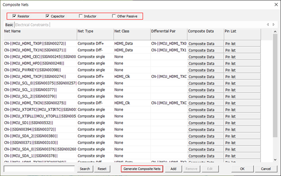
The Properties > Composite Nets menu provides versatile ways to manipulate the Composite Nets
generation and manage features with many options and operations illustrated
below.Figure 4.
Manage Composite Nets :
Selecting Composite Components: In the Composite Component Area,
choose the components you want to use to create composite nets. Two nets
connected by the selected component will be modeled as a composite net.
Generating Composite Nets: Once you've selected a composite
component, use the Generate Composite Nets function to display the
composite nets in the result area.
Manual Addition: If needed, you can manually add specific nets to be
composited by using the Add menu.
Remove or Edit: You can remove or edit a composite net result by
clicking Remove or Edit.
Edit Dialog: Double-click on a composite net to open the Edit dialog,
where you can modify the Net Type, Net Class, and
Electrical Constraints.