Make Board Paneling GUI
- Object Definition: Define the object to be duplicated.
- Component: Include components placed in PCB data.
- Except Component: Exclude duplicate components. Exclude components
can be specified in the String Filter Set Up
dialog.
Figure 1. 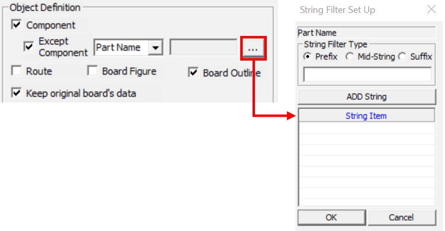
- Route: Include Route in PCB data.
- Board Figure: Include Board Figure in PCB data.
- Board Outline: Include Board Outline in PCB data.
- Keep original board’s data: Keep the original board outline of PCB data without deletion when the Board Outline option is not selected.
- Selected Area Only: Specify the PCB data area to be duplicated.
- Select Rect: Select the rectangular area as the duplicated area.
- Select Area: Select a polygon area as the duplicated area.
- Placement: Define where the duplicated objects are placed.
- Mirror: Create the duplicated original PCB data by mirroring.
- Mirror X: Mirroring the board based on the X axis.
- Mirror Y: Mirroring the board based on the Y axis.
Figure 2. 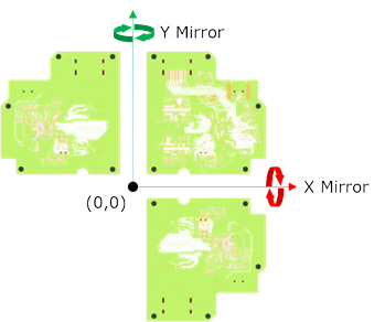
- Mirror: Create the duplicated original PCB data by mirroring.
- Rotation: Create the duplicated original PCB data by rotation.
- Rotation Angle: Enter the angle to be rotated. The rotate direction
is counterclockwise.
Figure 3. 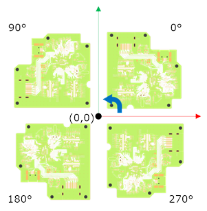
- Rotation Angle: Enter the angle to be rotated. The rotate direction
is counterclockwise.
- dX/dY: Define the X and Y coordinates where the duplicated PCB data is placed. The origin coordinate of the original PCB data is used as the reference point.
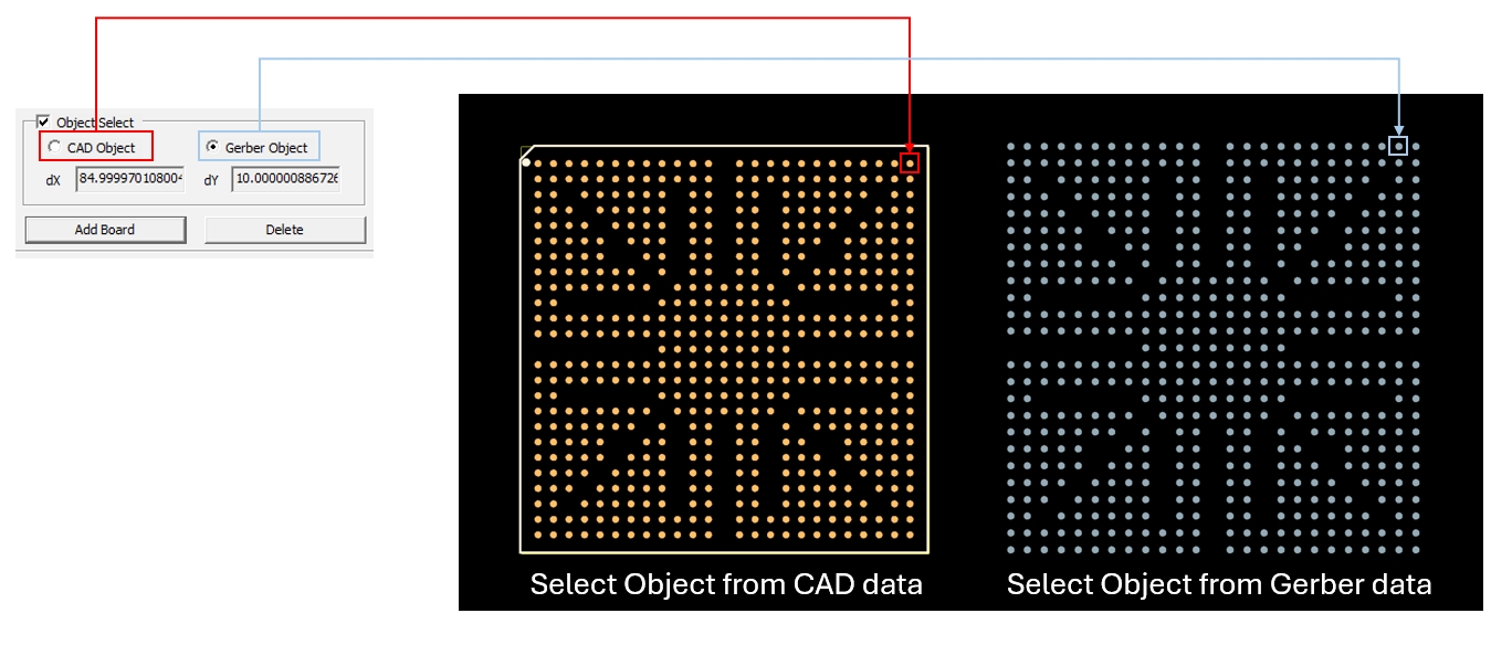
- Object Select: Automatically calculate the movement coordinates by selecting
the pad of the PCB data and the pad of the Bare Board Gerber (Metal Mask)
data in an array.
- Cad Object: Select the reference pad on the PCB design data.
- Gerber Object: Select a pad object that matches the pad selected in CAD data.
- dX/dY: Define the X and Y coordinates where the duplicated PCB data
is placed. The origin coordinate of the original PCB data is used as
the reference point.
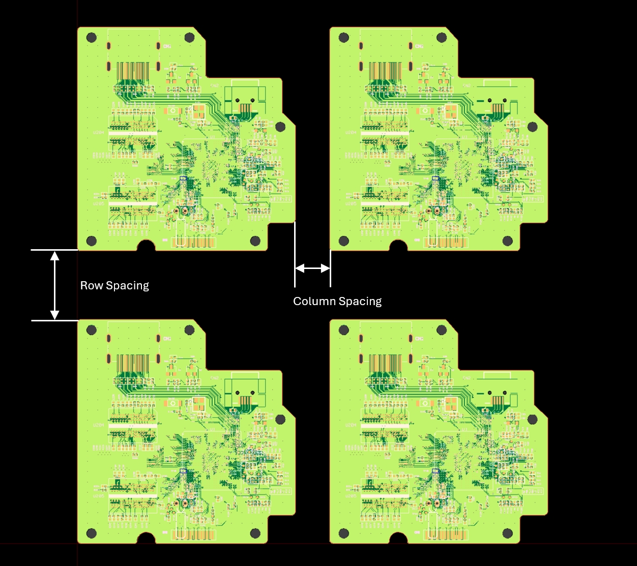
- Array: This function is used when the duplicated data is to arrange with the
same distance and angle.
- Column Spacing: Set the Vertical spacing of the sub-boards using the
spacing value.
- Count: Set the number of sub boards to be duplicated in Vertical directions.
- Row Spacing: Set the Horizontal spacing of the sub-boards using the
spacing value.
- Count: Set the number of sub boards to be duplicated in
Horizontal directions.
- Count: Set the number of sub boards to be duplicated in
Horizontal directions.
- Preview: Preview of information set in Placement.
- Apply: Apply the information set in Placement.
- Initialize: Revert the applied result to the previous state.
- Column Spacing: Set the Vertical spacing of the sub-boards using the
spacing value.
- After Complete Paneling, Remove Gerber Data: Delete the Gerber layer after completing the array paneling in the case of using Gerber data.
- Define Panel Outline: Set the margin of the panel outline.
- Left/Right Margin
- Top/Bottom Margin
- Rounded Corner: Set the corners of the panel outline to be rounded or
chamfered.
- Top Left/Right
- Bottom Left/Right

- Line Width: Specify the width of Panel Outline.
- Get Panel Outline from Gerber: Designate the line selected in Gerber data as the Panel Outline.
- Apply: Apply Panel Outline information.
- Initialize: Revert the applied result to the previous state.
- Export PDF: Move the applied Placement information and the defined Panel Outline information to the Export Settings window.