Example 2: Radome with FSS
This document shows an example to create a radome with FSS. The table below resumes the parameters taken into account in the following example:
| Data | Definition | Values |
|---|---|---|
| Frequency | Simulation Frequency | 10 GHz |
| Material | Teflon | Er = 1.9 |
| Thickness | Radome thickness | 4 mm |
| FSS | Radome FSS | Cross |
Create a new MOM project. To do that, click on New Project button and select the MOM module.
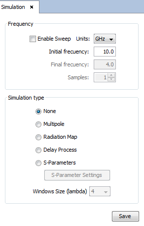
Set the frequency. Click on Simulation –> Parameters menu and then the Simulation panel is open on right side of screen. Set the frequency to 10 GHz and click on Save button before closing the panel.
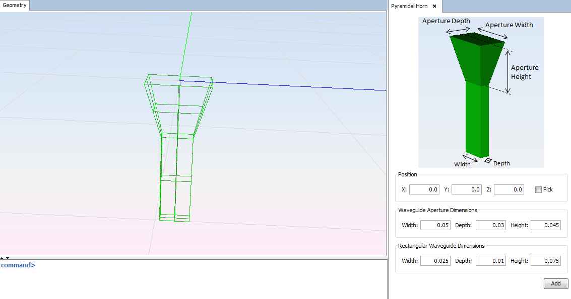
Set the feeding. Click on Source -> Primitive Antennas -> Horn -> Pyramidal Horn menu and click on Add with default parameters. Note The default parameters of the horn are calculated automatically for the simulation frequency.
Set the Radome Geometry. To create the radome geometry follow this steps:
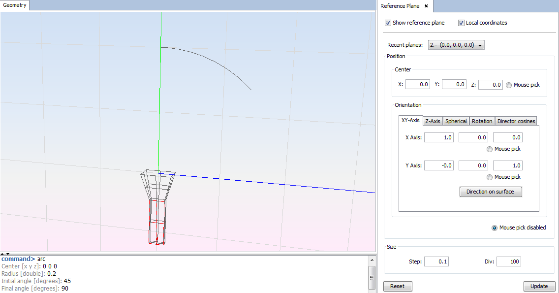
1. Change Y axis of Reference Plane to Z axis. Click on View -> Reference Plane and set Y-axis to (0.0, 0.0, 1.0) and then click on Update button.
2. Draw an arc with the following parameters. Click on Geometry -> Curve -> Arc.
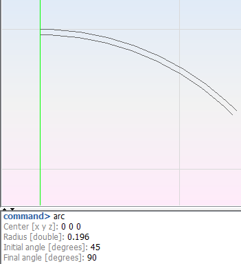
3. Draw another arc with the following parameters. The thickness between the two arcs is 4mm.
4. Click on Reset button of the Reference Plane panel.
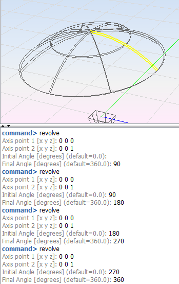
5. Revolve arcs. Click on Geometry -> Surface -> Revolve and select the two arcs. For a better meshing create the surfaces with 90 degrees of revolution.
Set the FSS. To create a conformed FSS on the radome surface folow this steps:
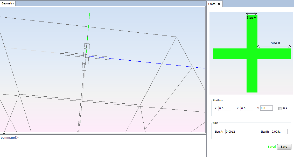
1. Draw the FSS Element. Click on Source -> Radome -> FSS Primitives -> Crosses -> Cross and click on Save button with default parameters. The FSS Element must be on XY plane and centered on (0.0, 0.0, 0.0).
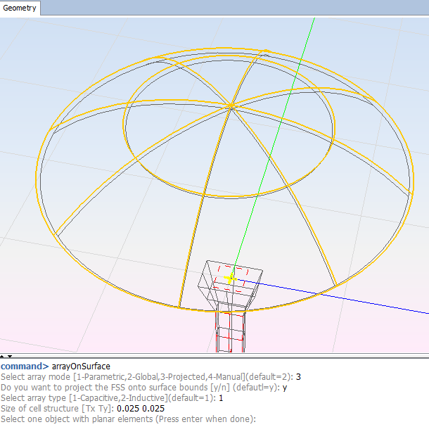
2. Select the upper surfaces of the radome and click on Edit -> Geometric Operations -> Arrays -> Array On Surface.
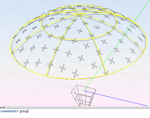
3. Group radome interfaces. Select the upper and lower surfaces of the radome and group them separately.
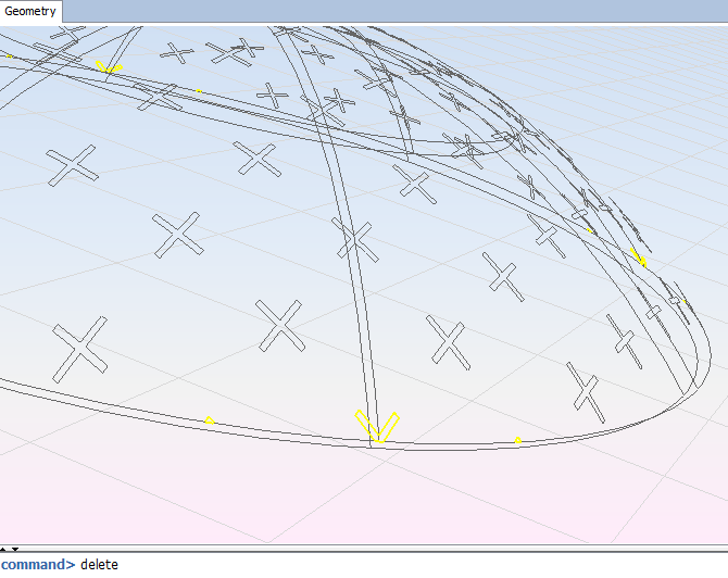
4. Remove the crosses that are not closed and the FSS Element. Select crosses and click on Edit -> Explode and then select the individual cross and click on Edit -> Delete.
5. Group the crosses again. Crosses can be selected by clicking on the tree surfaces folder. Click on Edit -> Group.
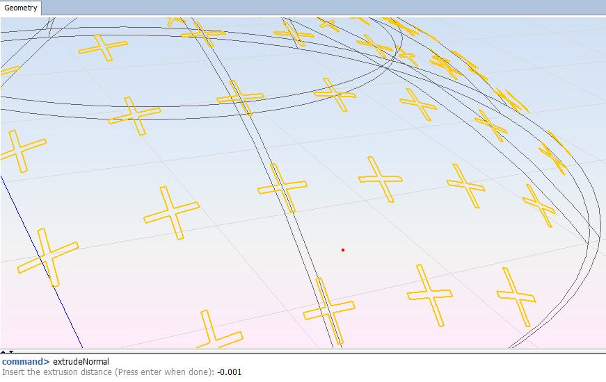
6. It is possible to give a thickness to the crosses. In this case select the crosses and click on Geometry -> Solid -> Extrude Normal. Set the thickness to 1mm.
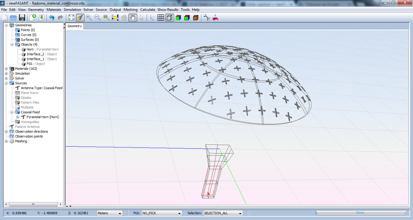
7. Group the crosses with their thickness and rename the objects as you can see in the following image.
Configure Radome Parameters. To finish defining the radome follow the next steps:
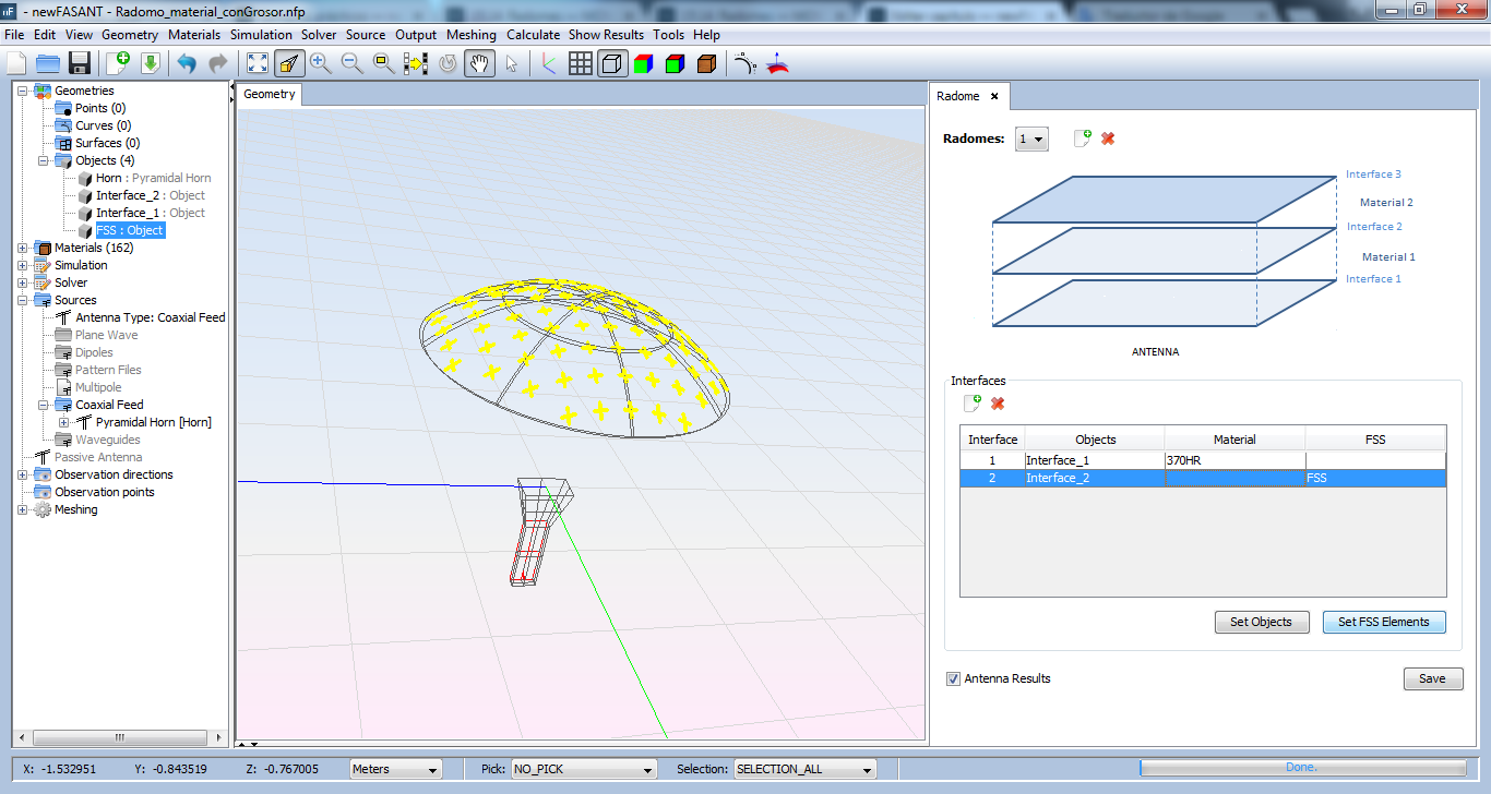
1. Click on Source -> Radome -> Define Radome menu and add a radome.
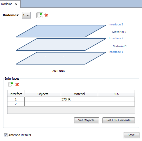
2. Select the object of Interface 1 (lower) and the first row in Radome panel and then click on Set Objects button. Repeat the process with the object of Interface 2.
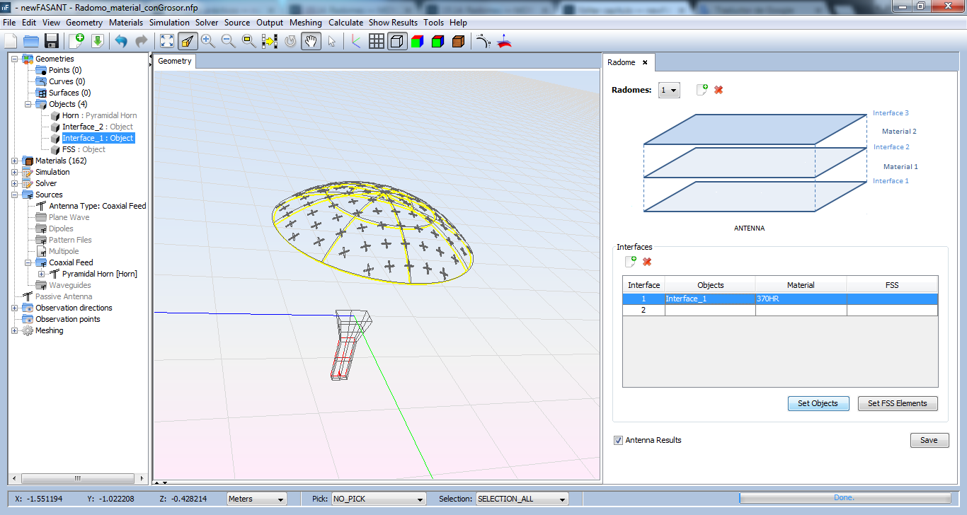
3. Selects the FSS object and the second interface in Radome Panel. Click on Set FSS Elements button.
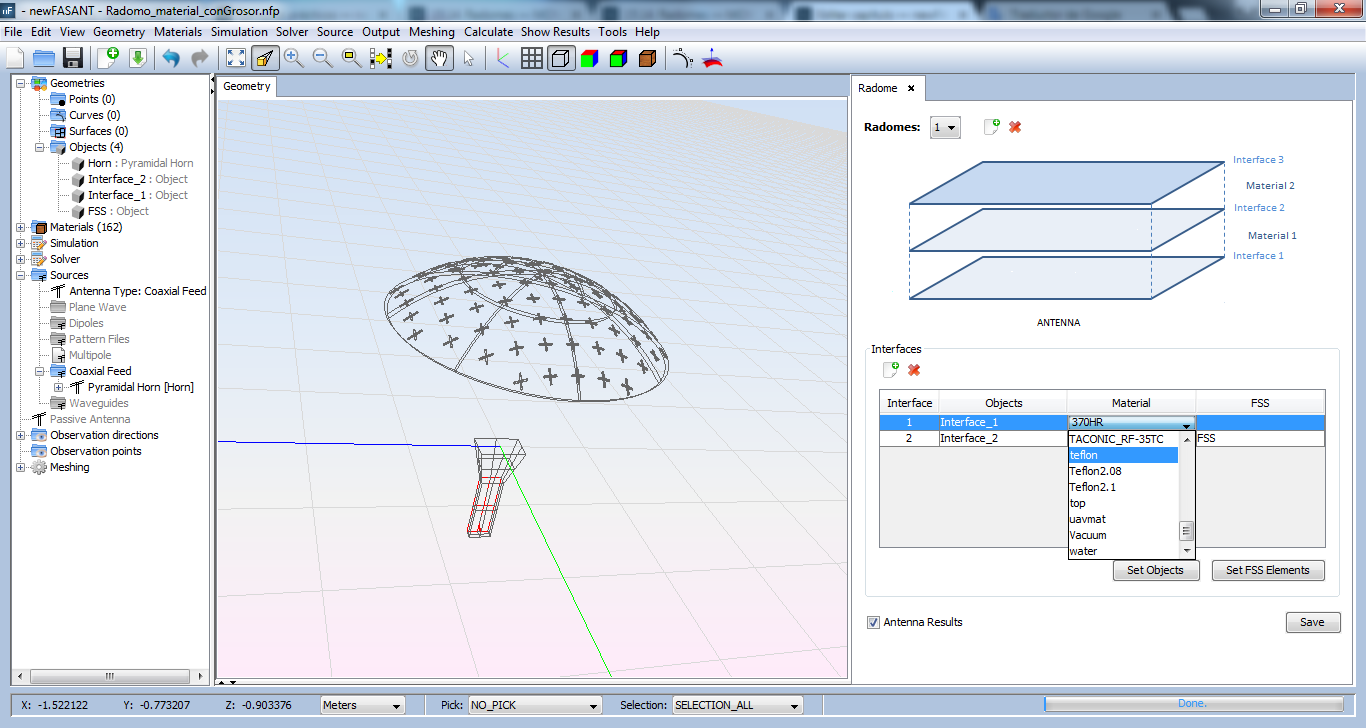
4. Select the material 'Teflon' on Interface 1. Click on Save button of Radome panel. Note The material of interface 1 corresponds to the material between the two interfaces.
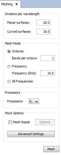
Meshing Geometry. Click on Meshing -> Create Mesh and set planar and curved divisions to 20. Click on Mesh button.
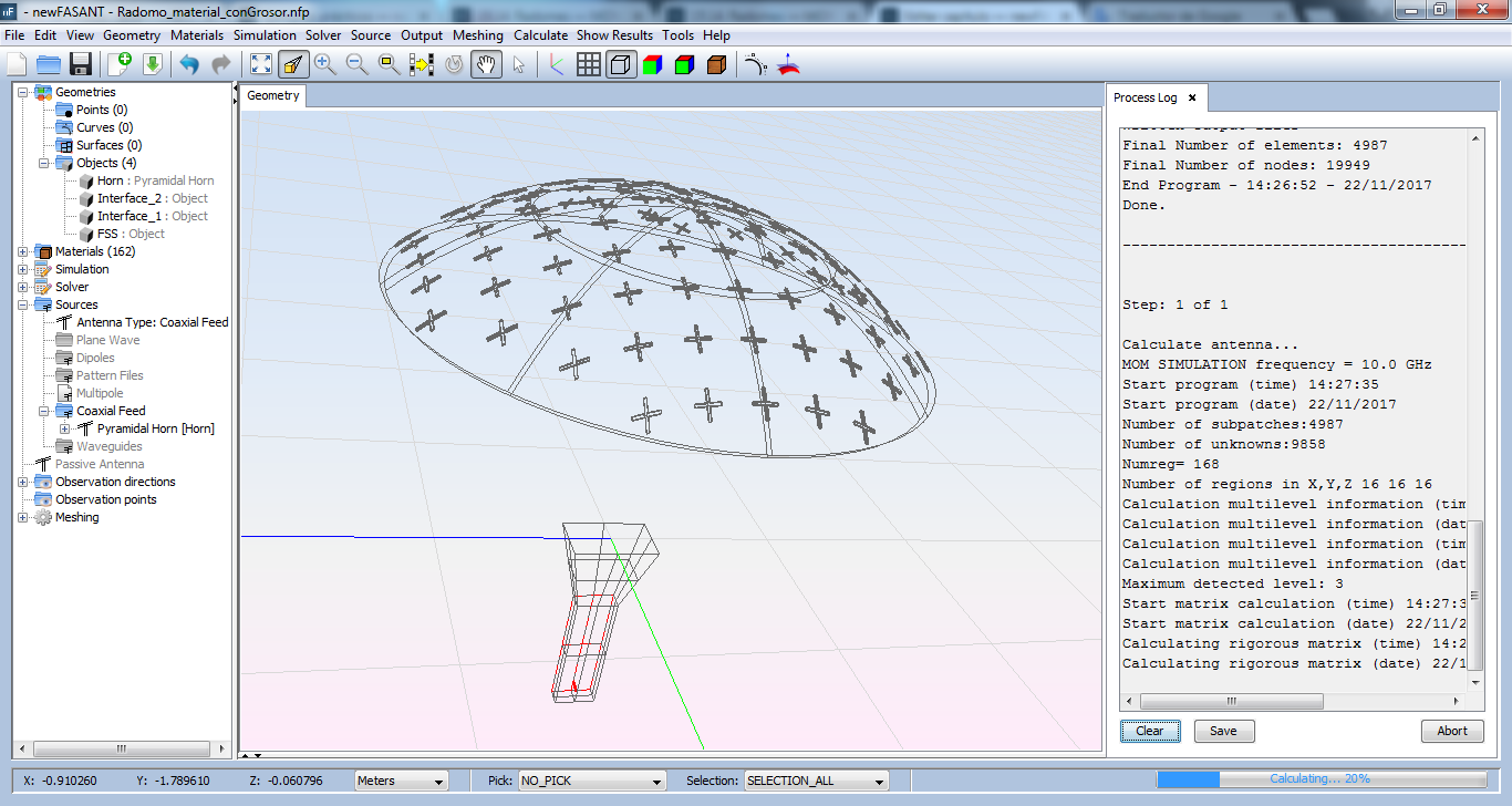
Start Simulation. Click on Calculate -> Execute.
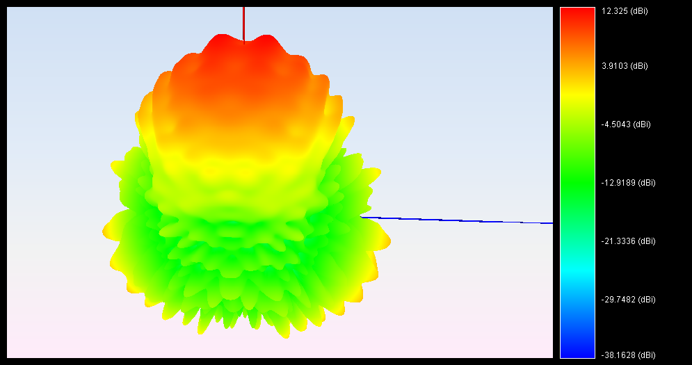
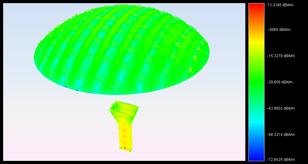
Results
Radiation Pattern: