The "Define Interface Radome" option allows the user to generate a radome, including
interfaces and materials. Every radome layer is bounded by two surrounding
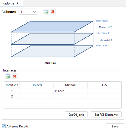
interfaces and the material defined on the inner interface. Click on to add a new radome. Figure 1. Interface Radome Definition Tab
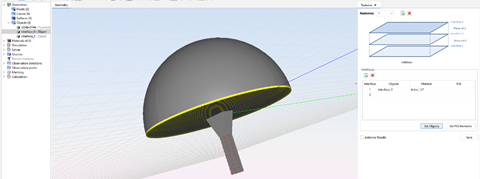
"Interface 1" is the most inner one, select its geometry and select the interface on
the table, then click on Set Objects.
Repeat the process with all interfaces. Then select the layer material clicking on
the material cell.Figure 2. Set Objects on Interface 1
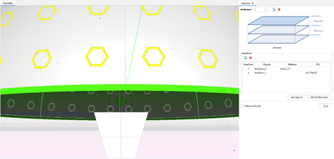
FSS geometry can be added to the interface. First, create the FSS geometry using
arrayOnSurface
command. Select its geometry and select the interface on the table, then click on
Set FSS Elements.Figure 3. Set FSS Elements on interface 2
The "Antenna Results" checkbox enables meshing and calculating the antenna system
without the radome structure. This option enables "Insertion Losses" and "Boresight
Error" and allows to compare the results when the radome is considered or not.
Click on "Save" button to save the radome parameters.
 to add a new radome.