
/FAIL/ALTER
Block Format Keyword An advanced nonlinear stress-based failure criteria for glass applications such as a windshield.
The failure stress is described by parameters defining micro-cracks and crack propagation speed. With the X-FEM approach, the stress is set to zero perpendicular to the crack direction.
Format
| (1) | (2) | (3) | (4) | (5) | (6) | (7) | (8) | (9) | (10) |
|---|---|---|---|---|---|---|---|---|---|
| /FAIL/ALTER/mat_ID/unit_ID | |||||||||
| Exp_n | V0 | Vc | Ncycles | Irate | Iside | mode | |||
| Cr_foil | Cr_air | Cr_core | Cr_edge | grsh4N | grsh3N | ||||
| KIC | KTH | Rlen | Tdelay | Iout | |||||
| Kres1 | Kres2 | ||||||||
| Eta1 | Beta1 | Tau1 | Area_ref | ||||||
| Eta2 | Beta2 | Tau2 | |||||||
| Sig0 | P_scale | P_switch | |||||||
| (1) | (2) | (3) | (4) | (5) | (6) | (7) | (8) | (9) | (10) |
|---|---|---|---|---|---|---|---|---|---|
| fail_ID |
Definition
| Field | Contents | SI Unit Example |
|---|---|---|
| mat_ID | Material identifier. (Integer, maximum 10 digits) |
|
| unit_ID | (Optional) Unit Identifier. (Integer, maximum 10 digits) |
|
| Exp_n | Crack growth exponent for subcritical
crack growth. Default = 16.0 (Real) |
|
| V0 | Crack growth velocity
for subcritical crack growth at
KIC. Default = 0.0 (Real) |
|
| Vc | Maximum crack propagation velocity
glass. Default = 0.0 (Real) |
|
| Ncycles | Stress filtering period in cycles. Only
used when Irate=0. 2
(Integer) |
|
| Irate | Stress rate filtering method.
(Integer) |
|
| Iside | Strain rate dependency option.
|
|
| mode | Flag to switch failure propagation
models between neighbor elements.
(Integer) |
|
| Cr_foil | Crack depth at bottom surface. Default = 0.0 (Real) |
|
| Cr_air | Crack depth at top surface. Default = 1.0 (Real) |
|
| Cr_core | Crack depth in between bottom and
surface integration points. Default = 1.0 (Real) |
|
| Cr_edge | Crack depth at the edge elements of
windshield. Default = 1.0 (Real) |
|
| grsh4N | (Optional) Group identifier for 4 node
edge shell elements. Default = 0 (Integer) |
|
| grsh3N | (Optional) Group identifier for 3 node
edge shell elements. Default = 0 (Integer) |
|
| KIC | Fracture toughness. Default = 0.0 (Real) |
|
| KTH | Fatigue threshold. Default = 0.0 (Real) |
|
| Rlen | Reference length. Default = 1.0 (Real) |
|
| Tdelay | Relaxation time before removing
elements. Default = 0.0 (Real) |
|
| Iout | Activate exhaustive failure flag in
Engine output file.
(Integer) |
|
| Kres1 | Residual tensile stress scale factor in
first crack direction. Default = 0.0 (Real) |
|
| Kres2 | Residual tensile stress scale factor in
second crack direction. Default = 0.0 (Real) |
|
| Eta1 | Distribution parameters
on bottom surface. 10
(Real) |
|
| Beta1 | Distribution parameters
on bottom surface. 10 (Real) |
|
| Tau1 | Distribution parameters
on bottom surface. 10 (Real) |
|
| Area_ref | Reference element surface
area. (Real) |
|
| Eta2 | Distribution parameters
on top surface. 10 (Real) |
|
| Beta2 | Distribution parameters
on top surface. 10 (Real) |
|
| Tau2 | Distribution parameters
on top surface. 10 (Real) |
|
| Sig0 | Initial stress at glass
surface. (Real) |
|
| P_scale | Limits the definition interval of
selected distribution function. (Real, between 0.0 and 1.0) |
|
| P_switch | Distribution function interval:
|
|
| fail_ID | Failure criteria
identifier. 9 (Integer, maximum 10 digits) |
Example (Glass)
#RADIOSS STARTER
#---1----|----2----|----3----|----4----|----5----|----6----|----7----|----8----|----9----|---10----|
/UNIT/1
unit for mat
#              MUNIT               LUNIT               TUNIT
                  Mg                  mm                   s
#---1----|----2----|----3----|----4----|----5----|----6----|----7----|----8----|----9----|---10----|
/MAT/LAW36/72200103/1
Glass with linear hardening
#              RHO_I
             2.50E-9
#                  E                  NU           Eps_p_max               Eps_t               Eps_m
             70000.0                0.23                   0                   0                   0
#  N_funct  F_smooth              C_hard               F_cut               Eps_f
         1         1                   0                1650                   0
#  fct_IDp              Fscale   fct_IDE                EInf                  CE
         0                   0         0                   0                   0
#  fct_ID1   fct_ID2   fct_ID3   fct_ID4   fct_ID5
 722001021
#           Fscale_1            Fscale_2            Fscale_3            Fscale_4            Fscale_5
                1000
#          Eps_dot_1           Eps_dot_2           Eps_dot_3           Eps_dot_4           Eps_dot_5
                   0
#---1----|----2----|----3----|----4----|----5----|----6----|----7----|----8----|----9----|---10----|
/FAIL/ALTER/72200103/1
#              EXP_N                  V0                  VC   NCYCLES     IRATE     ISIDE      MODE
                16.0                 6.0             1520000         6         0         0         1
#            CR_FOIL              CR_AIR             CR_CORE             CR_EDGE    GRSH4N    GRSH3N
             0.00040             0.00100             0.00500                   0         0         0
#                KIC                 KTH                RLEN                TDEL      Iout
              23.717              7.9057                 1.0                   0         0
#              KRES1               KRES2
                   0                   0
#               ETA1               BETA1                TAU1            AREA_REF
                   0                   0                   0                   0
#               ETA2               BETA2                TAU2
                   0                   0                   0
#               SIG0             P_SCALE  P_SWITCH
                   0                   0         0
#---1----|----2----|----3----|----4----|----5----|----6----|----7----|----8----|----9----|---10----|
/FUNCT/722001021
Function for glass
#                  X                   Y
                 0.0               500.0
                 1.0               550.0
#---1----|----2----|----3----|----4----|----5----|----6----|----7----|----8----|----9----|---10----|
#enddata
Comments
- This failure criteria is using the maximum stress as failure criterion. It is computed based on the strength of the material determined by initial cracks and the crack propagation velocity. Depending on mode switch flag, different failure propagation models between neighbor elements may be used.
- When
Irate=0, an exponential moving average filter is
used, and the filtered stress is:Where,
- This failure model is compatible only with under-integrated shell elements (Ishell =24 and Ish3n =2 are recommended) and not compatible with fully integrated shells. Also, although there is no restriction of the shell property that can be used, it is only compatible with one layer shell models.
- The elements defined in the groups grsh4N and grsh3N should be along the edge of the windshield and will receive specific failure weakening.
- This failure model is applied to shell
elements that sandwich a polyvinyl butyral (PVB) solid element layer using coincident
nodes. The entire assembly models a windshield.
Figure 1. Windshield finite element model 
Figure 2. Windshield model - entire assembly 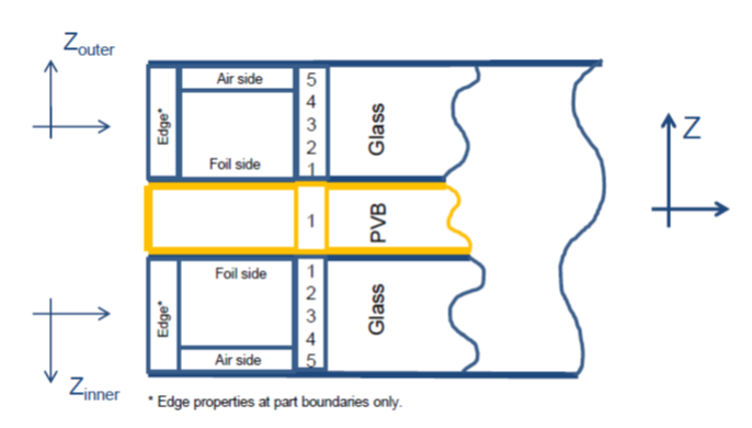
- The shell elements using this failure model should be oriented so that their normals point away the from the middle PVB.
- The shell elements should have an offset applied to correctly model bending. This can be done using /PROP/TYPE51 Ipos=4.
- The fracture limit depends on the location and the fracture state of surrounding elements. 1
- The fail_ID is used with /STATE/BRICK/FAIL and /INIBRI/FAIL and /PERTURB/FAIL/BIQUAD. There is no default value. If the line is blank, no value will be output for failure model variables in the /INIBRI/FAIL (written in .sta file with /STATE/BRICK/FAIL for brick and with /STATE/SHELL/FAIL for shell).
- Ch. Brokmann extension 2 defines additional fracture criteria for external glass
surfaces only. It introduces initial stress on the glass surface, due to mechanical or
chemical treatment. Statistical evaluation of micro flaws in the glass surface allows to
define a probability of fracture using left-truncated Weibull stochastic distribution:
with = 1,2 for bottom and top surface
Truncation point yields the well-known two-parameter Weibull distribution. The Brokmann model calculates the randomly oriented initial flaws in the glass and distributes them over all finite elements with different lengths and geometry. Crack growth may be expressed by the following differential equation:
Where, is a flaw geometry factor obtained using Weibull distribution.
Integral of Equation 3 will yield actual crack size, strongly dependent on stress rate. Actual stress intensity factors can be calculated and used in the fracture criteria.
The interest of Brokmann’s model is that depending on the distribution parameters and failure stress value, it is possible to estimate the stochastic probability of failure.Figure 3. 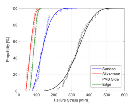
After running a sufficient number of simulations with random initialization of glass flaws return a possibility to estimate a probability to reach a given value of the head injury criterion (HIC).Figure 4. 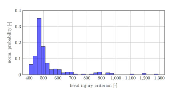
- Flag Irate is automatically set to 0 when Ch. Brokmann criterion is used. It is then necessary to define the number of cycles for the stress filtering interval using exponential average.