
AD_Converter
Simple n-bit analog to digital converter
![]()
Library
Modelica/Electrical/Analog/Ideal
Description
Simple analog to digital converter with a variable resolution of n bits.It converts the input voltage ppin.v-npin.v to an n-vector of type Logic(9-valued logic according to IEEE 1164 STD_ULOGIC). The input resistance between positive and negative pin is determined by Rin.Further effects (like input capacities) have to be modeled outside the converter, since this should be a general model.
The input signal range (VRefLo,VRefHi) is divided into 2^n-1 equally spaced stages of length Vlsb:=(VRefHi-VRefLo)/(2^n-1).The output signal is the binary code of k as long as the input voltage takes values in the k-th stage, namely in the range fromVlsb*(k-0.5) to m*(k+0.5). This is called mid-tread operation. Additionally the output can only changeits value if the trigger signal trig of type Logic changes to '1' (forced or weak).
The output vector is a 'little-endian'. i.e., that the first bit y[1] is the least significant one (LSB).
This is an abstract model of an ADC. Therefore, it can not cover the dynamic behaviour of the converter.Hence the output will change instantaneously when the trigger signal rises.
Parameters
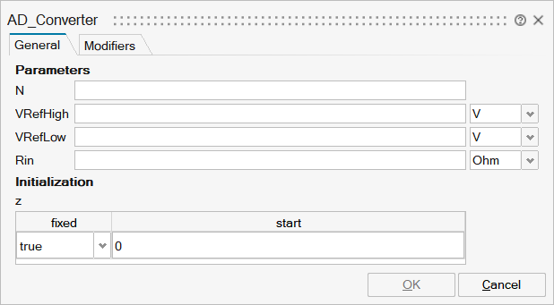
| Name | Label | Description | Data Type | Valid Values |
|---|---|---|---|---|
mo_N | N | Resolution in bits - output signal width | Scalar | |
mo_VRefHigh | VRefHigh | High reference voltage | Scalar | |
mo_VRefLow | VRefLow | Low reference voltage | Scalar | |
mo_Rin | Rin | Input resistance | Scalar | |
mo_z | z | z | Structure | |
mo_z/fixed | fixed | Cell of scalars | true | |
mo_z/start | start | Cell of scalars |
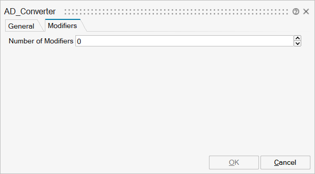
| Name | Label | Description | Data Type | Valid Values |
|---|---|---|---|---|
mo__nmodifiers | Number of Modifiers | Specifies the number of modifiers | Number | |
mo__modifiers | Modifiers | Add new modifier | Structure | |
mo__modifiers/varname | Variable name | Cell of strings | 'u' | |
mo__modifiers/attribute | Attribute | Cell of strings | 'start' | |
mo__modifiers/value | Value |
Ports
| Name | Type | Description | IO Type | Number |
|---|---|---|---|---|
p | implicit | Positive electrical pin (input) | input | 1 |
n | implicit | Negative electrical pin (input) | output | 1 |
y | implicit | Digital output | output | 2 |
trig | implicit | Trigger input | input | 2 |