 Package HydraulicsByFluidon.Components.Resistors
Icon for standard packages
Package HydraulicsByFluidon.Components.Resistors
Standard package icon.
Extends from Modelica.Icons.Package (Icon for standard packages).
| Name | Description |
|---|---|
IdealResistor | Ideal Resistor |
IdealResistorVariable | |
LocalResistance | Local Resistance |
Orifice | Orifice |
ResistorAlphaDA | |
ResistorTableAx | |
ResistorTableQp | |
ResistorTableQpx | |
Throttle | Throttle |
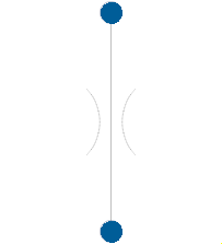 Model HydraulicsByFluidon.Components.Resistors.IdealResistor
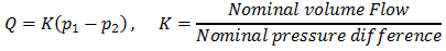
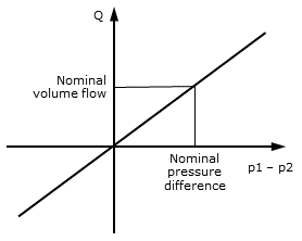
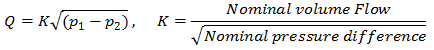
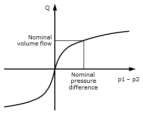
The component IdealResistor is a model of a flow resistance that behaves either as an orifice or a throttle, depending on the parameter setting.
Both are parameterized by the parameters Nominal volume flow at Nominal pressure difference, measured with a fluid with Reference density.Throttle
Orifice
Extends from HydraulicsByFluidon.Components.Base.PartialResistorVariable.
| Type | Name | Default | Description |
|---|---|---|---|
Boolean | forwardFluidProperties | true | Forward fluid properties between ports |
TResistorTypes | resistorType | HydraulicsByFluidon.Types.TResistorTypes.Orifice | Type of the resistor |
VolumeFlowRate | NominalVolumeFlow | 5e-4 | Nominal volume flow |
Pressure | NominalPressureDifference | 500000 | Nominal pressure difference |
Density | ReferenceDensity | 860 | Reference density |
| Type | Name | Description |
|---|---|---|
FluidPort | fluidPortA | Hydraulic port A |
FluidPort | fluidPortB | Hydraulic port B |
 Model HydraulicsByFluidon.Components.Resistors.IdealResistorVariable
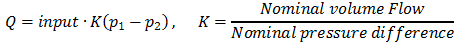
The component IdealResistorVariable is a model of a flow resistance that behaves either as an orifice or a throttle, depending on the parameter setting.
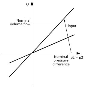
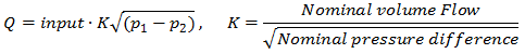
Flow is adjusted via the input signal with nominal flow (as given by Nominal volume flow at Nominal pressure difference) corresponding to an input value of 1 (relative adjustment).
Both are parameterized by the parameters Nominal volume flow at Nominal pressure difference, measured with a fluid with Reference density.Throttle
Orifice
The default relationship between input signal and flow rate of the resistor is linear, but can be changed through the use of a 1D look-up table. The look-up table is provided either manually or by importing a text file. If the parameter Table is provided by file is set to false, the manually entered datapoints from Manually provided look-up table will be used. If it is set to true, the table Table name on file from the file File where look-up table is stored will be utilized.
The text file must follow a specific syntax such that it can be read by Modelica. The input values as well as the output values must lie within the range from 0 to 1. An output value of 1 (100 %) corresponds to a fully-opened resistor. An example for a properly formatted text file with two tables is given in the figure below:
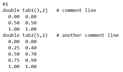
A table is declared by its datatype (e. g. double), followed by the table name (e. g. tab1) and its dimensions in brackets (e. g. (5,2)). As can be seen, multiple tables can be defined in the same text file. The table declaration is followed by the actual data. The first column of the table represents the input of the 1D table, whereas the second column lists the corresponding output values. The input values of the table must be in increasing order. The component interpolates linearly between the listed input values. More information regarding the format of tables can be found at CombiTable1Ds.
Extends from HydraulicsByFluidon.Components.Base.PartialResistorVariable.
| Type | Name | Default | Description |
|---|---|---|---|
Boolean | forwardFluidProperties | true | Forward fluid properties between ports |
TResistorTypes | resistorType | HydraulicsByFluidon.Types.TResistorTypes.Orifice | Type of the resistor |
VolumeFlowRate | NominalVolumeFlow | 5e-4 | Nominal volume flow |
Pressure | NominalPressureDifference | 500000 | Nominal pressure difference |
Density | ReferenceDensity | 860 | Reference density |
Boolean | tableFromFile | false | Table is provided by file |
String | fileName | "NoFile" | File where look-up table is stored |
String | tableName | "NoName" | Table name on file |
Real | manualTable[:,:] | [0,0; 1,1] | Manually provided look-up table |
| Type | Name | Description |
|---|---|---|
FluidPort | fluidPortA | Hydraulic port A |
FluidPort | fluidPortB | Hydraulic port B |
input RealInput | u |
 Model HydraulicsByFluidon.Components.Resistors.Orifice
The component Orifice is a model of a sharp-edged fluid resistance with a - to a large extent - root-like relationship between the flow rate and the pressure difference pA - pB acting on the component. The flow rate is independent of the viscosity of the hydraulic fluid.
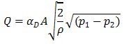
It is parameterized by the geometric parameters Diameter and Flow Coefficient alphaD.
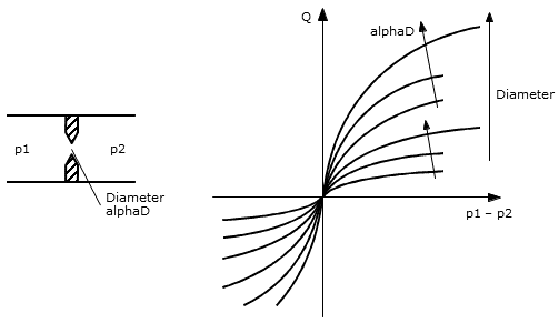
The Orifice is suitable for modeling an orifice opening, if the ratio of its length l to its diameter d is comparatively small (approx. l/d < 1.5).
The density of the hydraulics fluid is considered.
Extends from HydraulicsByFluidon.Components.Base.HydTwoPortVertical.
| Type | Name | Default | Description |
|---|---|---|---|
Length | diameter | 0.001 | Diameter |
Real | alphaD | 0.6 | Flow coefficient alphaD |
Boolean | forwardFluidProperties | true | Forward fluid properties between ports |
| Type | Name | Description |
|---|---|---|
FluidPort | fluidPortA | Hydraulic port A |
FluidPort | fluidPortB | Hydraulic port B |
 Model HydraulicsByFluidon.Components.Resistors.Throttle
The component Throttle is a model of a fluid resistance with to a large extent linear shaped dependence of the VolumeFlow on the pressure difference pA-pB connected to the component.
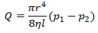
It is parameterized by the geometric parameters Diameter and Length. The kinetic viscosity of the fluid and its density are considered in their temperature dependency.
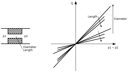
The Throttle is suitable for modeling a bore, if the ratio of its length l to its diameter d is comparatively large (approx. l/d > 10). It does not take any inductance into consideration. If desired, a PipeWithoutCapacity or a Pipe is the correct component instead.
Extends from HydraulicsByFluidon.Components.Base.HydTwoPortVertical.
| Type | Name | Default | Description |
|---|---|---|---|
Length | diameter | 0.001 | Diameter |
Length | length | 0.01 | Length |
Boolean | forwardFluidProperties | true | Forward fluid properties between ports |
| Type | Name | Description |
|---|---|---|
FluidPort | fluidPortA | Hydraulic port A |
FluidPort | fluidPortB | Hydraulic port B |
 Model HydraulicsByFluidon.Components.Resistors.LocalResistance
The component LocalResistance is a model of a flow resistance that represents the local pressure loss, which is typically calculated with the Pressure loss coefficient zeta.

Diameter is used for calculation of flow velocity v.
Values of Pressure loss coefficient can be found in literature, e. g. in I.E. Idelchik, Handbook of Hydraulic Resistance.
In the following tables standard values for the resistance coefficient Zeta are given. It is distinguished between bends (without marked radius of curvature R) and elbows (with considerable radius of curvature R), circular cross-sections are always assumed:
Bend
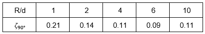
For bends with distinct radius of curvature R the resistance coefficient Zeta changes depending on the angle of curvature phi according to the formula:

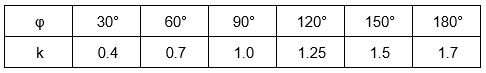
From the first table the values for Zeta 90deg depending on the ratio radius of curvature R to tube diameter d can be taken. The second table specifies values for the factor k depending on the angle of curvature phi (where appropriate interpolation is necessary).
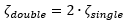
At multiple bends, the following equations can give clues for the calculation of Zeta:
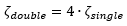
Double bend (two bends arranged semicircular):
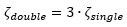
Room crooked (two bends arranged angular to each other):
Floor crooked (two bends arranged s-shaped):
Elbow
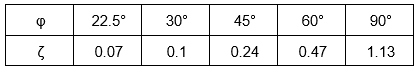
For bends without marked radius of curvature R, Zeta can be taken out of the following table and/or can be computed by interpolation:
Extends from HydraulicsByFluidon.Components.Base.PartialResistorBase.
| Type | Name | Default | Description |
|---|---|---|---|
Real | Zeta | 1 | Pressure loss coefficient |
Length | D | 0.032 | Diameter |
Boolean | forwardFluidProperties | true | Forward fluid properties between ports |
| Type | Name | Description |
|---|---|---|
FluidPort | fluidPortA | Hydraulic port A |
FluidPort | fluidPortB | Hydraulic port B |
 Model HydraulicsByFluidon.Components.Resistors.ResistorTableQp
The component ResistorTableQp is a model of a flow resistance. It is parameterized by a 1D look-up table which provides the volumetric flow rate (counted positive for flow from port A to port B) as a function of pressure drop (difference between pressures ports A and B). The component is predestined for integration of measured data into a simulation model.
Since the component calculates a mass flow rate, the user has to enter a Reference density which matches the density at which the flow rate was determined.
The look-up table is provided by importing a text file or can be given manually in the dialog. If the parameter Table is provided by file is set to false, the datapoints from Manually provided look-up table will be used. If it is set to true, the table from the text file will be utilized. The text file must follow a specific syntax such that it can be read by Modelica. The input pressure difference (provided in Pa) must cover negative as well as positive values if the resistor should be used for both flow directions. The resulting flow rate has to be provided in m³/s. An example for a properly formatted text file with two tables is given in the figure below:
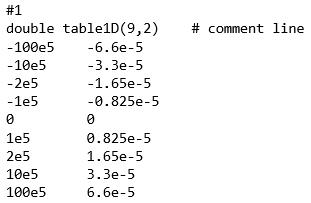
A table is declared by its datatype (e. g. double), followed by the table name (e. g. table1D) and its dimensions in brackets (e. g. (9,2)). Multiple tables can be defined in the same text file. The table declaration is followed by the actual data. The first column of the table represents the input of the 1D table, whereas the second column lists the corresponding output values. The input values of the table must be arranged in increasing order. The component interpolates linearly between the listed input values. More information regarding the format of tables can be found at CombiTable1Ds.
Extends from HydraulicsByFluidon.Components.Base.PartialResistorBase.
| Type | Name | Default | Description |
|---|---|---|---|
Boolean | tableFromFile | false | Table is provided by file |
String | fileName | "NoFile" | File where look-up table is stored |
String | tableName | "NoName" | Table name on file |
Real | manualTable[:,:] | [-2e+7,-5e-4; 0,0; 2e+7,5e-4] | Manually provided look-up table |
Density | ReferenceDensity | 860 | Reference density |
Boolean | forwardFluidProperties | true | Forward fluid properties between ports |
| Type | Name | Description |
|---|---|---|
FluidPort | fluidPortA | Hydraulic port A |
FluidPort | fluidPortB | Hydraulic port B |
 Model HydraulicsByFluidon.Components.Resistors.ResistorTableQpx
The component ResistorTableQpx is a model of an adjustable flow resistance. It is parameterized by a 2D table which provides the volumetric flow rate (counted positive for flow from port A to port B) as a function of pressure drop (difference between pressures ports A and B) and input signal. The component is predestined for integration of measured data into a simulation model.
Since the component calculates a mass flow rate, the user has to enter a Reference density which matches the density at which the flow rate was determined.
The look-up table is provided by importing a text file. The text file must follow a specific syntax such that it can be read by Modelica. The input pressure difference (provided in Pa) must cover negative as well as positive values if the resistor should be used for both flow directions. Both the input pressure difference and the input signal must be arranged in increasing order. The resulting flow rate has to be provided in m³/s. An example for a properly formatted text file with two tables is given in the figure below:
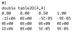
A table is declared by its datatype (e. g. double), followed by the table name (e. g. table2D) and its dimensions in brackets (e. g. (4,4)). Multiple tables can be defined in the same text file. The table declaration is followed by the actual data. Except for the first matrix element which has to be equal to 0, the first column of the table represents the pressure drop, whereas the first row corresponds to the input signal. All pressure drop and input values must be arranged in increasing order. The component interpolates linearly between the listed values. More information regarding the formatting of tables can be found at CombiTable2D.
Extends from HydraulicsByFluidon.Components.Base.PartialResistorBase.
| Type | Name | Default | Description |
|---|---|---|---|
String | fileName | "NoFile" | File where look-up table is stored |
String | tableName | "NoName" | Table name on file |
Density | ReferenceDensity | 860 | Reference density |
Boolean | forwardFluidProperties | true | Forward fluid properties between ports |
| Type | Name | Description |
|---|---|---|
FluidPort | fluidPortA | Hydraulic port A |
FluidPort | fluidPortB | Hydraulic port B |
input RealInput | u |
 Model HydraulicsByFluidon.Components.Resistors.ResistorTableAx
The component ResistorTableAx is a model of a flow resistance that behaves like an orifice.
Based on the parameter Flow coefficient alphaD and a look-up table for the Cross-sectional area as a function of the input signal, the flow rate is calculated according to the formula given below:
The relationship between input signal and Cross-sectional area of the resistor is described by a 1D look-up table. The look-up table is provided by importing a text file or can be given manually in the dialog. If the parameter Table is provided by file is set to false, the datapoints from Manually provided look-up table will be used. If it is set to true, the table from the text file will be utilized. The text file must follow a specific syntax such that it can be read by Modelica. An example for a properly formatted text file with input signal and output area is given in the figure below:
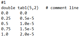
A table is declared by its datatype (e. g. double), followed by the table name (e. g. tab1) and its dimensions in brackets (e. g. (5,2)). Multiple tables can be defined in the same text file. The table declaration is followed by the actual data. The first column of the table represents the input of the 1D table, whereas the second column lists the corresponding output values. The input values of the table must be arranged in increasing order. The output of the table must be the cross-sectional area (in m²). The component interpolates linearly between the listed input values. More information regarding the format of tables can be found in the component CombiTable1Ds.
Extends from HydraulicsByFluidon.Components.Base.PartialResistorBase.
| Type | Name | Default | Description |
|---|---|---|---|
Boolean | tableFromFile | false | Table is provided by file |
String | fileName | "NoFile" | File where look-up table is stored |
String | tableName | "NoName" | Table name on file |
Real | manualTable[:,:] | [0,0; 1,2.444e-5] | Manually provided look-up table |
Real | alphaD | 0.6 | Flow coefficient alphaD |
Boolean | forwardFluidProperties | true | Forward fluid properties between ports |
| Type | Name | Description |
|---|---|---|
FluidPort | fluidPortA | Hydraulic port A |
FluidPort | fluidPortB | Hydraulic port B |
input RealInput | u |
 Model HydraulicsByFluidon.Components.Resistors.ResistorAlphaDA
The component ResistorAlphaDA is a model of a flow resistance that behaves like an orifice.
The flow rate is calculated according to the formula given below:
where  is given by the input AlphaDA.
Extends from HydraulicsByFluidon.Components.Base.PartialResistorBase.
| Type | Name | Default | Description |
|---|---|---|---|
Boolean | forwardFluidProperties | true | Forward fluid properties between ports |
| Type | Name | Description |
|---|---|---|
FluidPort | fluidPortA | Hydraulic port A |
FluidPort | fluidPortB | Hydraulic port B |
input RealInput | alphaDA | Input alphaD * A |