This tutorial demonstrates the Skill export feature of StarVision PRO and shows how to load the created Skill file into the Cadence environment.
As an example, we use the Spice file demo/spice/parity1.sp.
Please make sure that you have installed a license file which contains - in addition to one of the master GUI features - the feature gv-skillexport.
Overview
The following picture is an overview of the complete flow to export a schematic as Skill.
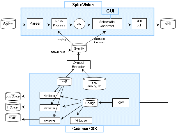
As a first step you need to use the Symbol Extractor to create a symbol library for StarVision PRO from your Cadence library, e.g. analogLib.
You need to manually define a mapping for Cadence library symbols to Spice models and sub-circuits.
This symbol library including the mappings is used by StarVision PRO while parsing your Spice file.
Now you are ready to write a Skill file and load it into Cadence.
This Skill creates the schematic drawing in Virtuoso, so you can continue your work in the Cadence environment, e.g. create a netlist to run simulation or modify the circuit.
FIRST STEP - Create a Symbol Library
In the first step you have to convert the symbols from your Cadence library (e.g. analogLib) to a symbol library for StarVision PRO using the Skill script cadence2symlib.il.
This script and additional documentation is contained in the symutils documentation directory.
Load the cadence2symlib.il script in Cadence Virtuoso using the command:
load("cadence2symlib.il")
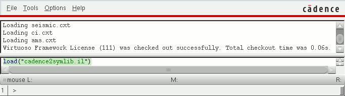
The cadence2symlib.il script adds a new entry "Export Symlib …" to the "Tools" menu.
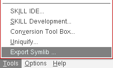
If you invoke this entry then the following dialog window will show up.
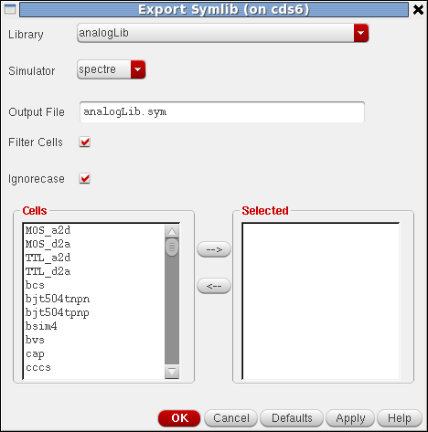
Please select your library and simulator to obtain CDF information in this form.
For this tutorial the analogLib and the basic libraries need to be exported.
You can also change the name of the output file. Press the OK button to run the export procedure.
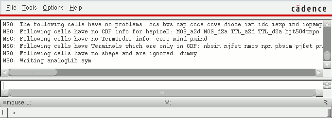
Please examine the output of the script in the Cadence command interpreter window output area to see if any symbols you intend to use have problems. These symbols should not appear e.g. with the annotation "no CDF info" or "no TermOrder info".
The generated symlib file needs some manual changes to get the correct mappings.
All spice and symio mappings are created as comments by the cadence2symlib.il script.
You need to edit the resulting symbol library with your favorite text editor (e.g. vi) and locate the mappings for the models cmosn, cmosp and the built-in CAP.
First remove the comment character # and then add the desired mapping.
The mapping can be done with the model name (including glob style wildcards) and the prefix like in this example.
The mapping to Power/Ground symbols is done with the additional symio lines.
spice nmos4        analogLib MN *
spice pmos4        analogLib MP *
spice cap          analogLib C  -
symio gnd          pg0 * * analogLib
symio vdd          pg+ * * analogLib
The mapping for interface ports can also be done with the symio lines in the basic.sym file.
symio iopin        inout * * basic
symio ipin         in    * * basic
symio opin         out   * * basic
A detailed description of the syntax of these lines can be found in the reference manual.
SECOND STEP - Load Design
Start StarVision PRO (if you are not familiar with the basics of StarVision PRO please refer to the Quickstart Guide).
Enable the visibility of all bulk pins. Select the menu entry.
To avoid off-grid placement of instance pins and therewith off-grid net routing, go to "Preferences" and switch on the option "Transistor Devices on Grid".
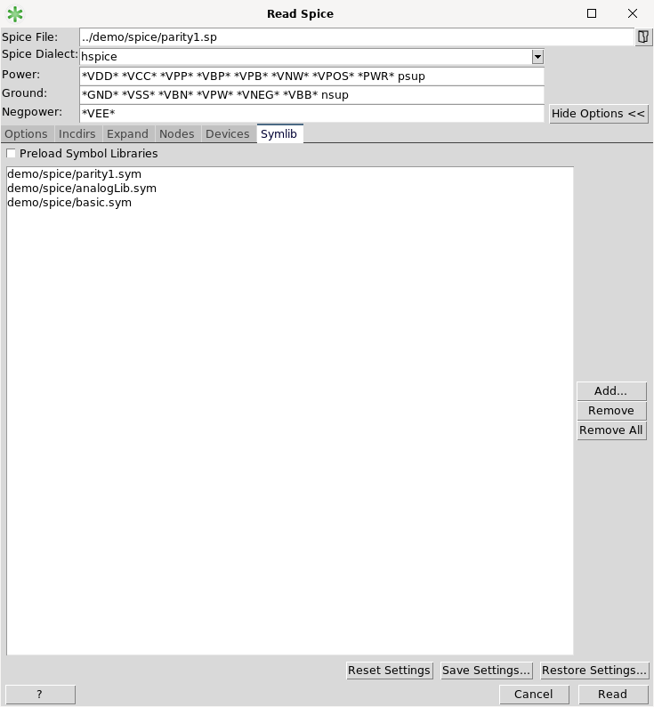
Open the Read Spice dialog and browse to the file demo/spice/parity1.sp.
Now show the options and select the Symlib tab in the advanced mode.
Add the two symbol libraries (analogLib.sym and basic.sym) you have created in the first step.
In addition to this you can also add the symbol library demo/spice/parity1.sym.
If you use another example: in case a sub-circuit in the Spice netlist has more pins than the symbol in the symbol library, the additional pins get hidden.
Switch to the Options tab and turn off Evaluate VSource to: Input.
This step is important if you intend to create a netlist to run a simulation.
Press the Read button to load the design parity1.sp with the just created symbol libraries from the analogLib and basic libraries.
THIRD STEP - Export Skill
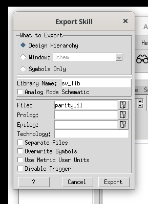
Select and enter an output file name, e.g. parity.il.
Press the Export button to write the Skill file.
FOURTH STEP - Load Skill into Cadence
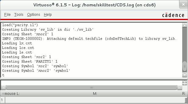
To load the Skill file you have created in the previous step, please type the following command into the Input Line of the Command Interpreter Window (CIW):
load("parity.il")
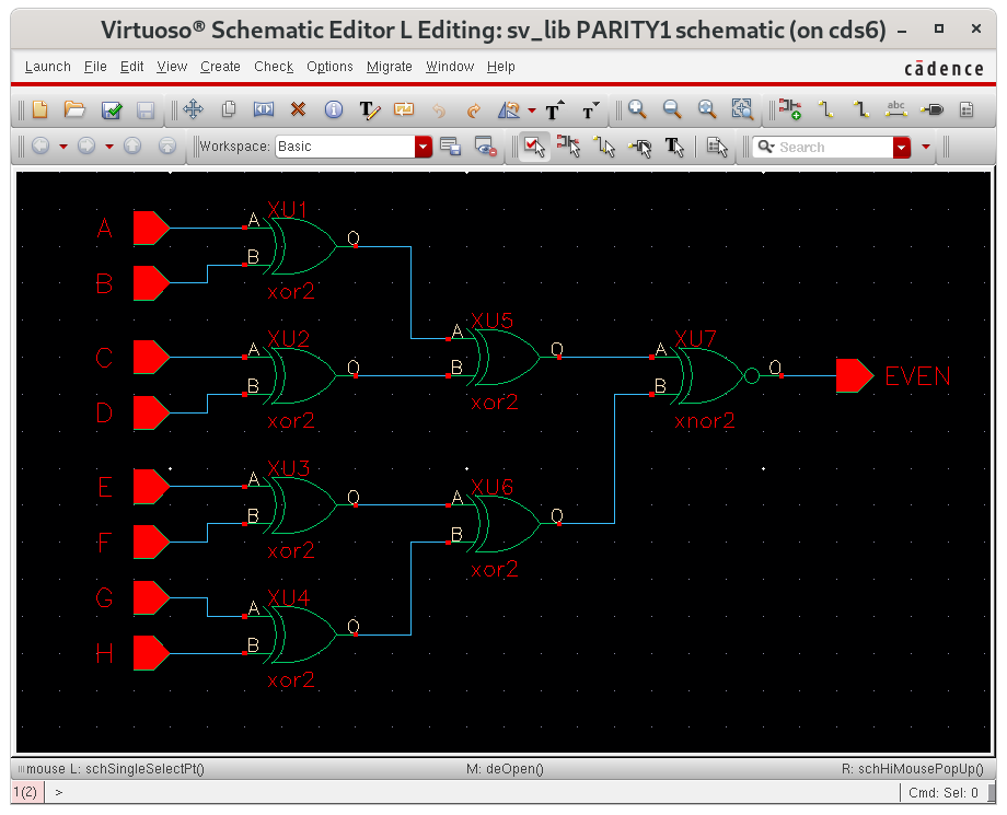
To view the created schematics use , select the library sv_lib, the cell PARITY1 and the view "schematic".
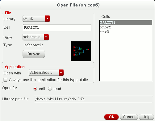
After pressing the OK button you can see the schematic in Cadence Virtuoso.
FIFTH STEP - Create Netlist
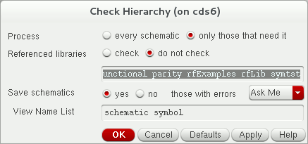
Before you can create a netlist you need to Check and Save the design. Therefore invoke from the Virtuoso window. This step can be automated by specifying an Epilog script.
After the check completes without errors invoke from the Virtuoso window . In the Analog Design Environment window, first define a simulator, e.g. Spectre, with and then select .
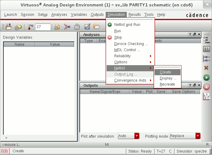
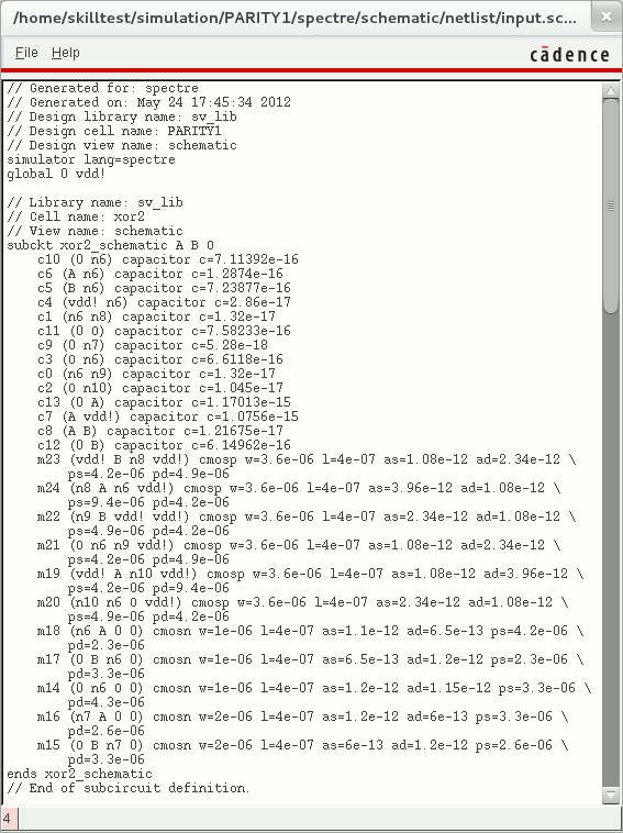
Here is a screenshot of the resulting Spectre netlist, based on the imported schematic.