RD-T: 3050 Simplified Car Pole Impact
To simulate frontal pole test with a simplified full car.
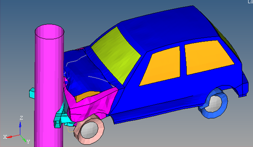
Figure 1.
- UNITS: Length (mm), Time (s), Mass (ton), Force (N) and Stress (MPa)
- Simulation time: Engine file (_0001.rad) [0 - 0.06 ms]
- An initial velocity of 15600 mm/s is applied on the car model to impact a rigid pole of radius 250 mm.
- Elasto-plastic Material /MAT/PLAS_JOHNS (WINDSHIELD)
[Rho_Initial] Initial Density = 2.5x10⁻⁹ton/mm3
[E] Young's Modulus = 76000 MPa
[nu] Poisson's Ratio = 0.3
[0] Yield Stress = 192 MPa
[K] Hardening Parameter = 220 MPa
[n] Hardening Exponent = 0.32
- Elasto-plastic Material /MAT/PLAS_JOHNS (STEEL)
[Rho_Initial] Initial Density = 7.9x10⁻⁹ton/mm3
[E] Young's Modulus = 210000 MPa
[nu] Poisson's Ratio = 0.3
[0] Yield Stress = 200 MPa
[K] Hardening Parameter = 450 MPa
[n] Hardening Exponent = 0.5
[SIG_max] Maximum Stress = 425 MPa
- Elasto-plastic Material /MAT/PLAS_JOHNS (RUBBER)
[Rho_Initial] Initial Density = 2x10⁻⁹ton/mm3
[E] Young's Modulus = 200 MPa
[nu] Poisson's Ratio = 0.49
[0] Yield Stress = 1e30MPa
[n] Hardening Exponent = 1
Model Files
Start HyperCrash
- Open HyperCrash.
- Set the User profile to RadiossV2023 and the Unit system to kN mm ms.kg.
- Set User Interface style as New.
- Set your working directory to where the downloaded file is located.
- Click Run.
- Click .
- In the input window, select full_car.nas.
- Click OK.
Create and Assign WINDSHIELD Material
-
Enter all the material data, as shown below.
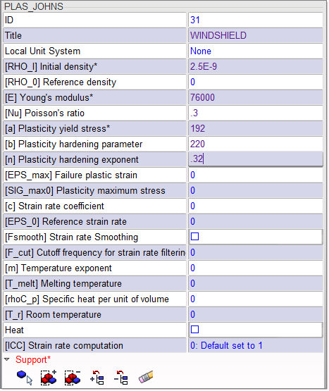
Figure 2. -
Click
 to show
only these parts.
to show
only these parts.
-
Right-click in the Support entry box and click
Selected Parts of Tree
 .
This icon allows adding the part selected in the tree to the selection. The selected parts will be highlighted in the modeling window.
.
This icon allows adding the part selected in the tree to the selection. The selected parts will be highlighted in the modeling window.
Create and Assign RUBBER Material
-
For Title, enter RUBBER. Enter all the material data, as
shown below.
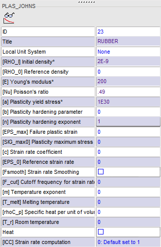
Figure 3. -
Click to show
only these parts.
-
Right-click in the Support entry box and click
Selected Parts of Tree
.
The selected parts will be highlighted in the modeling window.
Create and Assign STEEL Material
-
Enter all the material data, as shown below.
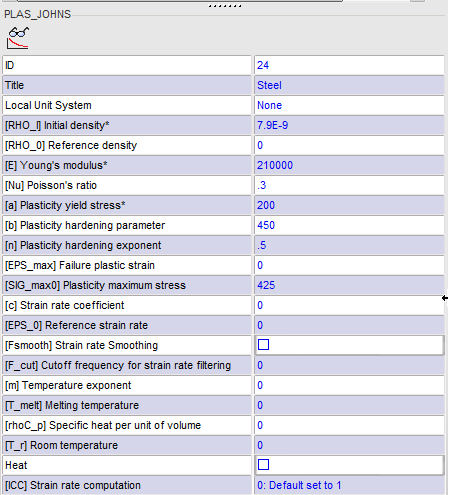
Figure 4. - Click
 to invert the tree selection.
 -
Click to show
all the parts except the ones made with glass and rubber.
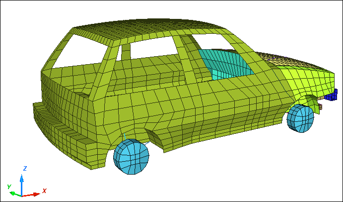
Figure 5. -
Right-click in the Support entry box and click
Selected Parts of Tree
 .
The selected parts will be highlighted in the modeling window.
.
The selected parts will be highlighted in the modeling window.
Create the Ground Rigid Wall
-
Enter the following values for M0 and M1:
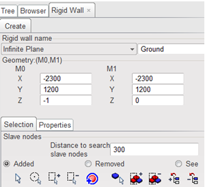
Figure 6.
Create Pole Rigid Wall
-
Enter the following values for M0 and M1:
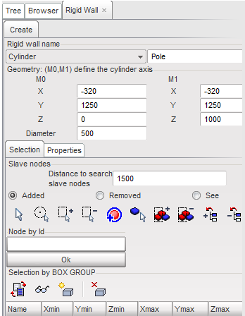
Figure 7.
Create an Interface for the Full Car
-
In the Model Display toolbar, click Display All
 to display the entire model.
-
Click in the [Main_id] Main field. Move the cursor to
the modeling window and right-click.
The menu shown in the image below should appear.
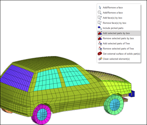
Figure 8. -
Choose the option Add selected parts by box
 and use
the mouse to drag a box to select the entire car in the modeling window.
and use
the mouse to drag a box to select the entire car in the modeling window.
Create an Interface between Engine and Radiator
Define Initial Velocities
- Click .
- In the Velocity list, right-click and select Create New.
- In the Title field, enter 35MPH.
- In the Tree window, highlight FULL_CAR.
- In the [Vx] field, enter 15600.
-
In the Initial Velocity tab, click in the [Gnod_id]
Support field. Move the cursor to the modeling window, right-click and select Add
selected parts of tree
.
- Click .
Define Time History Nodes
-
Click Isolate Tree Selections
.
-
Go back to the Time History panel and click Add/Remove nodes by
picking selection
 in the second
table.
in the second
table.
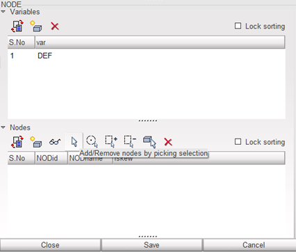
Figure 9. - Select six nodes on the rails, for example as shown in the following image:
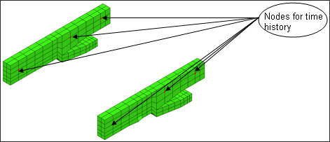
Figure 10.
Export the Model
-
Check the Control Cards, as shown in the images below.
Note: Make sure to save all control cards before editing the next.
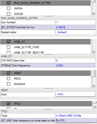
Figure 11.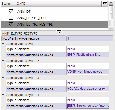
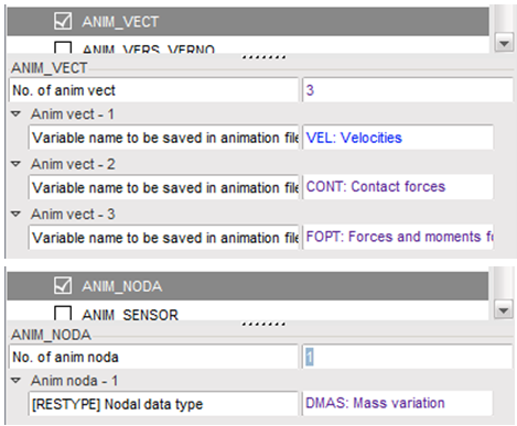
Figure 12.
Expected Results
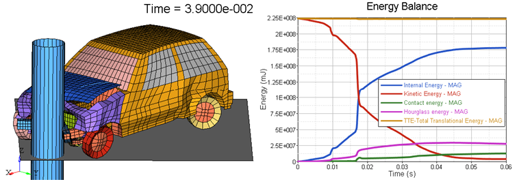
Figure 14. Final Deformation and Energy Balance Plot