Create an Area Junction
An Area junction is created between two subsystems. The junction is created on the surface that joins two subsystems.
-
From the Model ribbon, SEA Junctions group, select the tool.
Figure 1. 
The following guide bar is displayed:Figure 2. 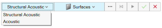
- From the guide bar's first drop-down menu, use Structural Acoustic when there is a structural subsystem between two cavities.
- From the second drop-down menu, select either Surfaces or Lines to represent the junction.
-
Select the geometry (based on the element type) to represent the junction and
click
 (Apply) to create a manual
connection.
(Apply) to create a manual
connection.
-
Use the Create Seam Junction
Entity Editor to update the junction's details.
Figure 3. 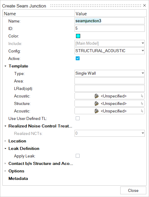
- Name
- Enter a unique name.
- ID
- Enter a unique ID.
- Config
- Specify the element type.
- Template Type
- Choose from the one of the following template types:
- Realized Noise Control Treatment
- Realized Noise Control Treatments are automatically added after solving. Realized NCTs are added only when there are NCTs assigned to SEA structural subsystems (plate and shell) connected to a cavity. These realized NCTs can be visualized on both 2D structural subsystems and SEA junctions.
- Location
- Select the surface.
- Leak Definition
- Select options as necessary.
- Contact b/n Structure and Acoustic
-
- Acoustic Subsystem > Layer Stiffness - Use Curve > Value
- Select a subsystem and enter a value or select Use Curve.
- Options
-
- Corrections for small areas > Mass law sound transmission
- By default, mass law sound transmission through structures separating two acoustic spaces is included in the SEAM connection. You can turn off this transmission, for example, to study the relative importance of mass law versus resonant transmission. In general, retain mass law transmission in the model.
- Z Translation > Added Mass PUA - Use Curve > Value
- Specify an added mass per area in the connection. The added mass decreases mass-law transmission though the structure.
- Insertion Loss (Above/Below/mass-law) - Use Curve > Value
- Define an insertion loss for the structural-acoustic coupling as either a constant value or a function versus frequency. Use the insertion loss to include the effects of a panel trim or barriers, which is defined as the difference in transmission loss for the bare structure and the treated structure. The first two options for Insertion Loss address the insertion loss from the structure to the acoustic spaces “above” and “below” the structure in the structural acoustic connection parameter form element boxes, respectively. The third option for Insertion Loss addresses the mass law transmission between the two acoustic spaces in the connection.
-
From the guide bar, select
Acoustic when two subsystems are directly
connected.
Figure 4. 
- Select either Surfaces or Points to represent the junction.
-
Select the geometry to represent the junction and click (Apply) to create manual connection.
-
Use the Create Seam Junction
Entity Editor to update the junction's details.
Figure 5. 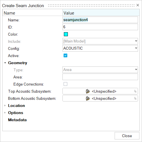
Use Acoustic junction when two subsystems are directly connected. Create an enclosed boundary using surfaces and convert into cavities using bounding options.- Name
- Enter a unique name.
- ID
- Enter a unique ID.
- Config
- Specify the element type.
- Geometry
-
- Type
- Keep Area as the default type.
- Area
- Enter the area of surface.
- Edge Connections
- Select to create edge connections.
- Top Acoustic Subsystem
- Select the acoustic subsystem.
- Bottom Acoustic Subsystem
- Select the acoustic subsystem.
- Location
- Select the surface.
- Options
- For Transmission Loss Type, select Transmission
Loss or Transmission
Coefficient.
- Transmission Loss or Transmission Coefficient
- Enter a user-defined transmission loss or transmission coefficient in dB or as a transmission coefficient in linear units. The relationship between the transmission loss and the transmission coefficient and the calculation of the coupling is described in the SEAM Reference Manual. See Acoustic Coupling with Known Transmission Loss.