Create a Structural Junction
Learn how to create a structural junction.
-
From the Model ribbon, SEA Junctions tool group, click the
Structural tool.
Figure 1. 
-
From the guide bar, select Lines
or Points to create the appropriate structural
connection.
Figure 2. 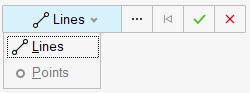
-
Select the geometry to represent the junction and click
Apply
 to create a manual connection.
- Use the Create Seam Junction Entity Editor to update the junction's details.
-
In the Create Seam Junction Entity Editor, verify that
Point is selected and define the following
options.
Figure 3. Create Seam Junction - Point 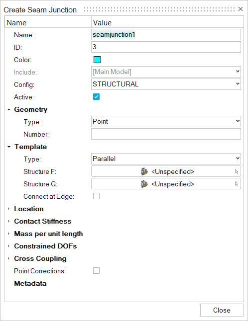
- Name
- Enter a unique name.
- ID
- Enter a unique ID.
- Config
- Specify the element type.
- Geometry
- Based on the element type, update geometry parameters.
- Number
- Enter a number.
- Template
- There are five types of templates for point junctions.
- Structure F
- Choose the first subsystem.
- Structure G
- Choose the second subsystem.
- Connect at Edge
- Click on square if the edges are to be connected.
- Location > Points/Lines
- Choose the point/line where the junction must be created.
- Element Contact Stiffness
- Use this option to model element contact stiffness (or element contact stiffness per unit length for line junctions) due to isolation systems. A blank or zero stiffness indicates no isolation is present for the DOF. Multiple elements in a connection may be isolated.
- The stiffness DOFs are listed in the isolated element's local
coordinate system (x,y,z) rather than the global connection
coordinates (X,Y,Z). The z axis is perpendicular to the element's
surface. See Masses and springs in the SEAM
Reference Manual for more details. Use the
Contact stiffness table to define all
stiffnesses.
Figure 4. Contact stiffness table 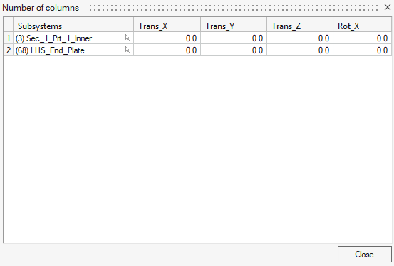
- Mass per unit length
- Translational and/or rotational masses at a junction (or mass/length for line junctions) are specified in this section. A junction mass changes the junction impedance, which may reduce or otherwise change the coupling between the elements in the connection. A translational mass changes the junction impedance for all translational degrees of freedom and a rotational mass changes the junction impedance for all rotational degrees of freedom. Frequency-dependent masses may be defined using a function.
- Constrained DOF
- Structural junctions typically involve translation and rotation through several degrees of freedom (DOF). This option allows you to block energy transmission through any DOF by constraining its motion. Physically, constraining a DOF in SEA means that the elements are free to move (translate or rotate) without causing a reaction or transmitting energy to other elements in the connection. This is opposite of the definition of a constrained DOF in an FEA model, where the elements at the DOF are rigidly constrained to have no relative motion.
- Cross Coupling
- Cross-coupling junctions connect the bending and in-plane subsystems within the same structure. This coupling is observed for real-world structures, even when the junction appears symmetric.