Dynamic Event
Use the Dynamic Event tool to define a dynamic (Modal Transient (MTRAN)) loadcase to solver and analyze squeak and rattle occurrences.
-
From the SnRPre ribbon, Setup
group, select the Dynamic Event tool from the Dynamic
Event tool group.
Figure 1. 
- Optional:
From the guide bar, click
 to define loadcase options.
- In the modeling window, select one or more nodes where the load should be applied.
- In the microdialog, select the required load type.
-
For Load Curve, select a curve type.
- Sine Sweep: Defines a SineSweep curve.
- From File: Import a load curve data in time domain from an external file.
- From PSD: Select a PSD curve and SnRD will convert it to time-domain.
- From Curve: Select curve(s) TABLED1, which already exists in session.
- Optional:
To visualize curves, click
 to open the Curve Editor
dialog.
to open the Curve Editor
dialog.
- Click Load Direction(s).
- Optional:
Click
 to define scaling and other options.
-
From the guide bar, complete one of the following
options:
- Click
 to create the dynamic event
and remain in the tool.
to create the dynamic event
and remain in the tool. - Click
 to create the dynamic event
and exit the tool.
to create the dynamic event
and exit the tool. - Click
 to exit the tool without
creating the dynamic event.
to exit the tool without
creating the dynamic event.
- Click
For more information, see Linear Transient Analysis in the OptiStruct User Guide and EIGRA in the OptiStruct Reference Guide.
Dynamic Event Options
Description of Dynamic loadcase options.
Load Curve
- Load Curve
-
- Sine Sweep
- Sinusoidal or Sine sweep is a sine function that gradually changes frequency over time.
- From File
- Use this option to import a file containing the load time history. SnRD supports loading either one, two, or three directions.
-
Note: When more than one load direction is created at the same time, SnRD will automatically create one Loadcase for each direction and one with all directions combined. Example: Applying a load on one node in three directions at the same time will create four loadcases.
Figure 2. 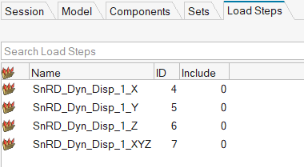
- From PSD
- PSD: Power Spectral Density
- From Curve
- Use already existing curves (TABLED1) in session as load curves. You will be prompted to select which curve is used for which direction.
- Undo Dynamic Event (
 )
) - Reverts the recently created dynamic event.
- You can revert the creation only if Curve Editor () is chosen.
- Curve Editor ()
- Launches the Curve Editor after creation of loadcase which allows for preview of the imported load curve(s).
- Modes
- Defines data for Eigenvalue analysis (EIGRL/EIGRA)
- Method
- Select Eigenvalue method, Lanczos or Amses.
- Frequency Range
- Define which frequency range to consider in evaluation.
- No of Modes to Extract
-
Set the number of modes to extract. If set to blank all modes in Frequency range are extracted.
- Damping
- Defines damping parameters (TABDMP1)
- Damping
- Define damping factor as constant over all frequencies or through a table.
- Method
- Set damping method.
- Time Step
- Defines Time Step Parameters (TSTEP)
- Auto Time Step
- Automatically extracts Time Step based on load curve.
- Auto No of Time Steps
- Automatically extracts number of time steps based on load curve.
- Output frequency
- Defines the output frequency of the results at the respective time steps.
- Output
-
- Displacement
- Output displacement on all E-Lines.
- Velocity
- Output Velocity on all E-Lines.
- GPForce
- Grid point force on all E-Lines.
The Supported format for loadcurve data is CSV and TXT and columns in file should be
organized depending on your selection as shown below:
- One direction-

TIME, DIR1-
Figure 3. 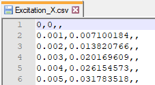
- Three Directions-

TIME, X, Y, Z- Three directions sample file is shown below-
Figure 4. 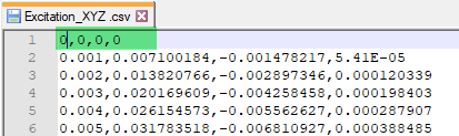
- Two Directions XY-

TIME, X, Y-
Figure 5. 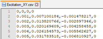
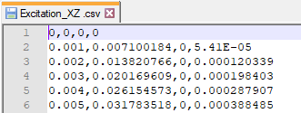
- Two Directions XZ-

TIME, X, Z-
Figure 6.