Manage E-Lines
Use the Manage E-Line tool to review and manage E-Lines.
At realization, the finite element entities at each evaluation point will be created. You can also review and edit all E-Lines in bulk in the Review E-Line dialog.
- Realize and Edit E-Lines
- Realize, review, and update interface parameters for one E-Line at a time.
- Review E-Lines
- Use the Review E-Line dialog to review, edit, and update parameters for all E-Lines and to map material compatibility data to squeak lines.
Realize and Edit E-Lines
Review, edit, and update interface parameters for one E-Line at a time.
-
From SnRPre ribbon, Setup group,
select the Manage E-Line tool.
Figure 1. 
-
From the guide bar, select an evaluation type:
- All E-Lines
- E-Lines of a specific type (squeak or rattle)
- Unrealized E-Lines
- Manually select an E-Line from the modeling window or use the arrows on the guide bar to review and edit one E-Line at a time.
- Optional:
Manually edit or update the parameters if needed.
Figure 2. 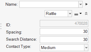
-
Complete one of the following options:
- Click
 to realize E-Lines and remain in the tool.
 - Click
 to realize E-Lines and exit the tool.
 - Click
 to exit the tool without
realizing E-Lines.
to exit the tool without
realizing E-Lines.
Note: Before proceeding to next step, all E-Lines should be realized and the necessary parameters should be updated.Unrealized E-Line(s) will be realized and, if they are edited, parameters will be updated. FE-entities representing the E-Line will be created. - Click
Review E-Lines
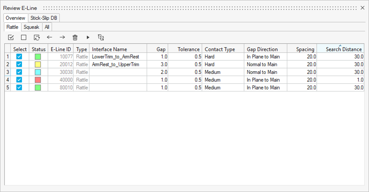
Use the Review E-Line dialog to review, edit, and update parameters for all E-Lines and map material compatibility data to squeak lines. Squeak Evaluation
- View all E-Lines in the model. E-Lines are split by type (Rattle, Squeak, and All) under the sub tabs. Each sub tab exposes only the relevant parameters for the selected type.
- Edit and update E-Line parameters for single or multiple E-Lines (see Manage E-Lines Options).
- Create interface names on the fly, review and update gap and tolerance values for interfaces, or map interface names from an imported DTS file.
- Map materials from Stick-Slip DB to squeak E-Lines.
-
From the SnRPre ribbon, Setup
group, select the Review E-Lines tool
from the Manage E-Lines tool group.
Figure 3.  The Review E-Line dialog opens.
Figure 4. 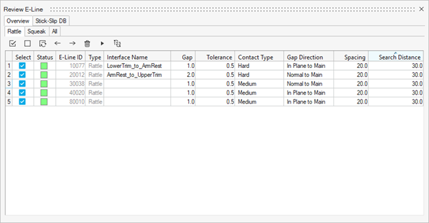
-
Click
 to delete the selected E-Lines from the model.
-
Click to realize the selected E-Lines in the model.
Note: When you edit or update a parameter for a realized E-Line, the line status changes to modified (blue) or unrealized (yellow). For such changes, you will have to realize the updated line. See Manage E-Lines Options for more information.
-
Click
 to renumber the selected E-Lines.
- Specify an interval.
-
Click to renumber the selected
E-Lines.
-
Click to close the renumbering
workflow.
Note: The last four digits of an ID cannot be edited and will be set and controlled automatically. The smallest E-Line ID is 10000.
Stick-Slip DB
Stick-Slip testing provides compatibility information for material pairs and supports squeak assessment in post-processing of E-Lines (Squeak Evaluation).
The idea behind mapping materials from Stick-Slip DB is to incorporate testing data without interfering with the materials of the FE model.
- Extract all material compatibility information from Stick-Slip DB on AMDC.
- Use the built-in DB from Squeak and Rattle Director to get (impulse rate)-1 values.
- Input data from in-house testing.
-
From the SnRPre ribbon, Setup
group, select the Review E-Lines tool
from the Manage E-Lines tool group.
Figure 5.
The Review E-Line dialog opens. -
Select the Stick-Slip DB tab.
Figure 6. 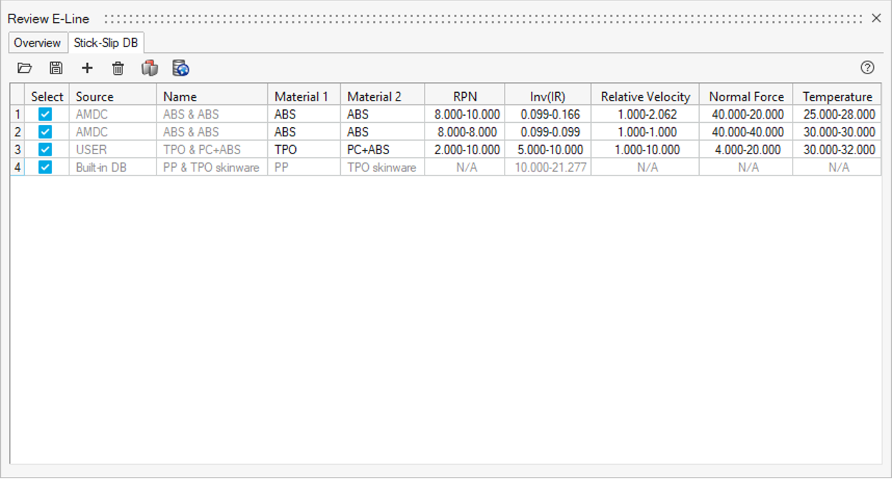
-
Click
 to open an existing Stick-Slip
DB file.
to open an existing Stick-Slip
DB file.
-
Click
 to export a
.csv file once created.
to export a
.csv file once created.
-
Click
 to add material pairs from
Stick-Slip DB on AMDC.
Learn more in Stick-Slip DB on AMDC.
to add material pairs from
Stick-Slip DB on AMDC.
Learn more in Stick-Slip DB on AMDC. -
Click
 to add
material pairs from built-in DB on Squeak and Rattle Director.
to add
material pairs from built-in DB on Squeak and Rattle Director.
-
Click to add the selected
material pair to the Stick-Slip.
Figure 7. 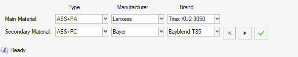 Note: Type is the only mandatory input. Manufacturer and Brand can be left blank if unknown. Furthermore, not all material combinations have a match, some combinations do not have a risk of squeak. The Impulse Rate range for these is 100-100.
-
Click
-
Click
 to add material pairs from
in-house testing.
Note: Only Material 1/Material 2 names and Inv(IR) are mandatory for further assessment. Other information is for awareness only and can be left blank if not available.
to add material pairs from
in-house testing.
Note: Only Material 1/Material 2 names and Inv(IR) are mandatory for further assessment. Other information is for awareness only and can be left blank if not available. -
Return to the Overview tab and map the material pairs to the squeak E-Line under the Material Pair column.
Figure 8. 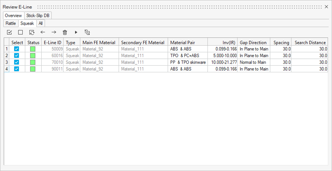
Manage E-Lines Options
The following options are available in the Review E-Line dialog.
- Status
- Contains the E-Lines realization status
 : realized E-Lines.
 : unrealized E-Lines. If the columns Type, Gap Direction, Spacing, and
Search Distance are modified, the E-Line status
changes to unrealized, meaning that the FE-entities will be recreated
once the E-Line is realized.
: unrealized E-Lines. If the columns Type, Gap Direction, Spacing, and
Search Distance are modified, the E-Line status
changes to unrealized, meaning that the FE-entities will be recreated
once the E-Line is realized. : modified E-Lines. If the columns Interface Name, Gap, Tolerance,
Inv(IR), and Contact type are modified, the E-Line
status changes to modified and there will be no impact on the
FE-entities once the E-Line is realized.
: modified E-Lines. If the columns Interface Name, Gap, Tolerance,
Inv(IR), and Contact type are modified, the E-Line
status changes to modified and there will be no impact on the
FE-entities once the E-Line is realized. : failed E-Lines. Increasing search distance typically resolves
failed E-Lines. If this is not the case, use the
Connector Browser for detailed error handling
and advanced control to fix problem.
: failed E-Lines. Increasing search distance typically resolves
failed E-Lines. If this is not the case, use the
Connector Browser for detailed error handling
and advanced control to fix problem.
- E-Lines ID
- A unique ID for each E-Line along with the number of connections for respective E-Lines (last digits).
- Type
- Defines what type of phenomena to evaluate along the line – rattle or squeak.
- Interface Name
- Enter a name or assign from imported DTS file (if used) to respective E-Line in model to map the GD&T data.
- Gap
- Gap value for the interface in the specified gap direction. This is defined based on the Gap assignment method.
- Tolerance
- Design tolerance for gap in the specified gap direction. This is defined based on the Gap Assignment method.
- (Impulse Rate)⁻¹ range
- Inverse of Impulse Rate range is a measure of the material pair compatibility. This is defined based on the material mapping and only applies to Squeak lines.
- Contact Type
- Define Contact type for the E-line. This is based on Youngs' modulus value of the Main and Secondary FE material.
- Gap Direction
- Realization Projection direction that controls creation of the local coordinate systems which determines the Gap direction.
- Spacing
- Value for the spacing between two adjacent Evaluation Points on an E-Line.
- Search Distance
- Value for search / gap tolerance between the selected Main-Secondary component.
- Main FE Material
- Assigned FE material for main component in the E-Line.
- Secondary FE Material
- Assigned FE material for secondary component in the E-Line.
- Material Pair
- Mapped Material Pair from Stick-Slip DB to the E-Line.