Align to Lines
Use the Line tool to project nodes or points to a line along a user-defined direction or the normal to the line selected, then remap or offset over selected reference entities.
-
From the secondary ribbon, click the Lines tool.
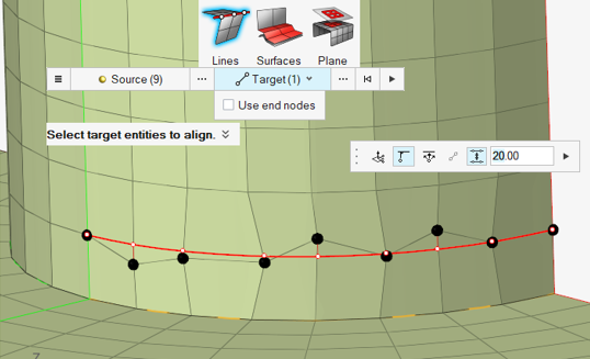
Figure 1. 
- Select ordered nodes, FE edges, or points as source geometry to align/project to onto target entities.
- Check Use end nodes to auto-detect end nodes based on your source selection and align between them. Otherwise, select target entities to align to.
-
Click
 Along Vector to define a single direction using the Vector
tool.
All of the entities are projected along this direction.
Along Vector to define a single direction using the Vector
tool.
All of the entities are projected along this direction. -
Use the icons in the microdialog further refine the
alignment:
 - Remap projected nodes to they are dispersed
evenly over the length of the line.
- Remap projected nodes to they are dispersed
evenly over the length of the line. - If two nodes or targets are selected, toggle
to make the connecting line finite/infinite.
- If two nodes or targets are selected, toggle
to make the connecting line finite/infinite. - Offset the target line by the specified
value
- Offset the target line by the specified
value
-
Click
 .
.
- Project source nodes on to a target line
Figure 2. 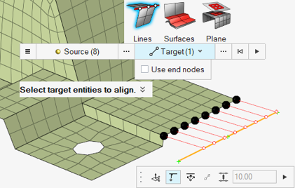
- Project nodes on to a smooth line (smooth lines can be defined using the
location entity)
Figure 3. 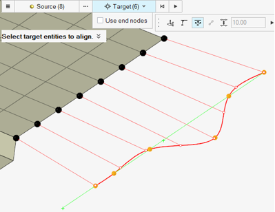
- Align nodes between start and end nodes
Figure 4. 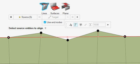
- Align nodes with respect to reference nodes
Figure 5. 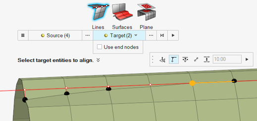
- Align + Remap
Figure 6. 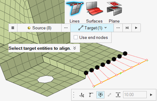
- Align + Offset
Figure 7.