Circuit
| SM PM IR | SM PM OR | SM WF ISP IR 3PH | SM RSM IR 3PH | IM SQ IR 3PH | IM SQ OR 3PH | DC PM IR | |
|---|---|---|---|---|---|---|---|
| Circuit |
Overview
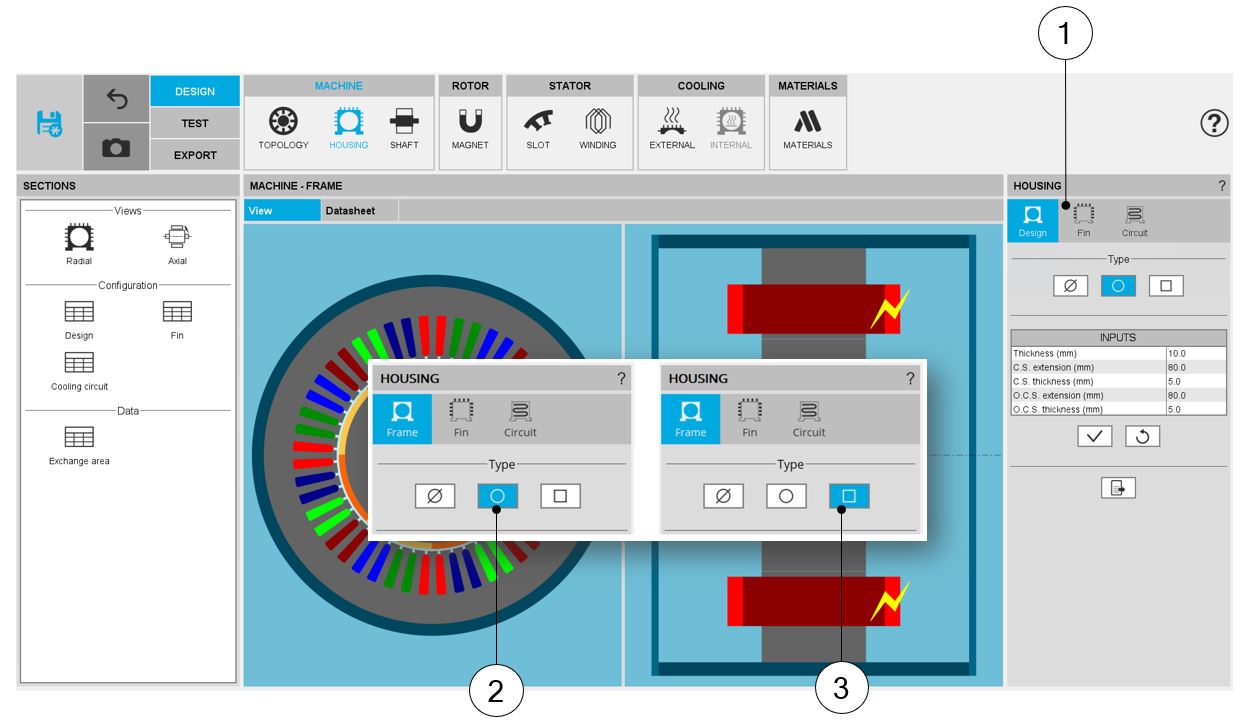
Access to the “Cooling circuit” area is unlocked when a frame is defined, when its shape is circular or square.
 |
|
| How to unlock the “Cooling circuit” area? | |
| 1 | “Cooling circuit” area is unlocked (as well as the “Fin” area). |
| 2 | Selection of a circular shape frame. |
| 3 | Selection of a square shape frame. |
Type of cooling circuits
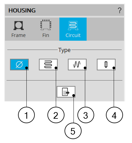
The tools available in the housing tab allow defining the cooling circuit topology.
Four choices are available to define this topology: None, Zig-Zag, solenoid or User shape.
By default, fin type is set to “None”. There is no cooling circuit.
 |
|
| Cooling circuit type available | |
| 1 |
Default setting : Cooling circuit type is « None » Theres is no cooling circuit inside the housing. |
| 2 | Button to select Zig-Zag type cooling circuit. |
| 3 | Button to select Solenoid type cooling circuit. |
| 4 | Button to select User type cooling circuit. |
| 5 | Icon to export fin data into *.txt or *.xls files. |
Zig-Zag type cooling circuit
–––––
Area
 |
|
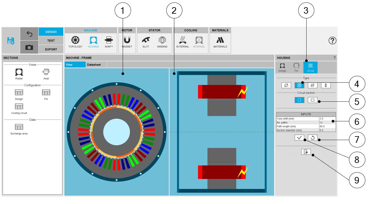
| Zig-Zag type cooling circuit - Design area | |
| 1 | Radial view of the motor, including the housing topology with cooling circuit topology and dimensions. |
| 2 | Axial view of the motor, including the housing topology with cooling circuit topology and dimensions. |
| 3 | The section Circuit (Cooling circuit) is selected to define the type and dimensions of the cooling circuit. |
| 4 | Selected button to define the topology of the cooling circuit. |
| 5 | Two sections can be considered: Circular (default one) and rectangular. |
| 6 | User input parameters to define the cooling circuit characteristics. For more information see below. |
| 7 | Button to restore default input values. |
| 8 | Button to apply inputs. Pressing the enter key twice applies inputs too. |
| 9 | Icon to export frame data into *.txt or *.xls files. |
–––––
Topology with circular section tubes - Inputs
 |
|
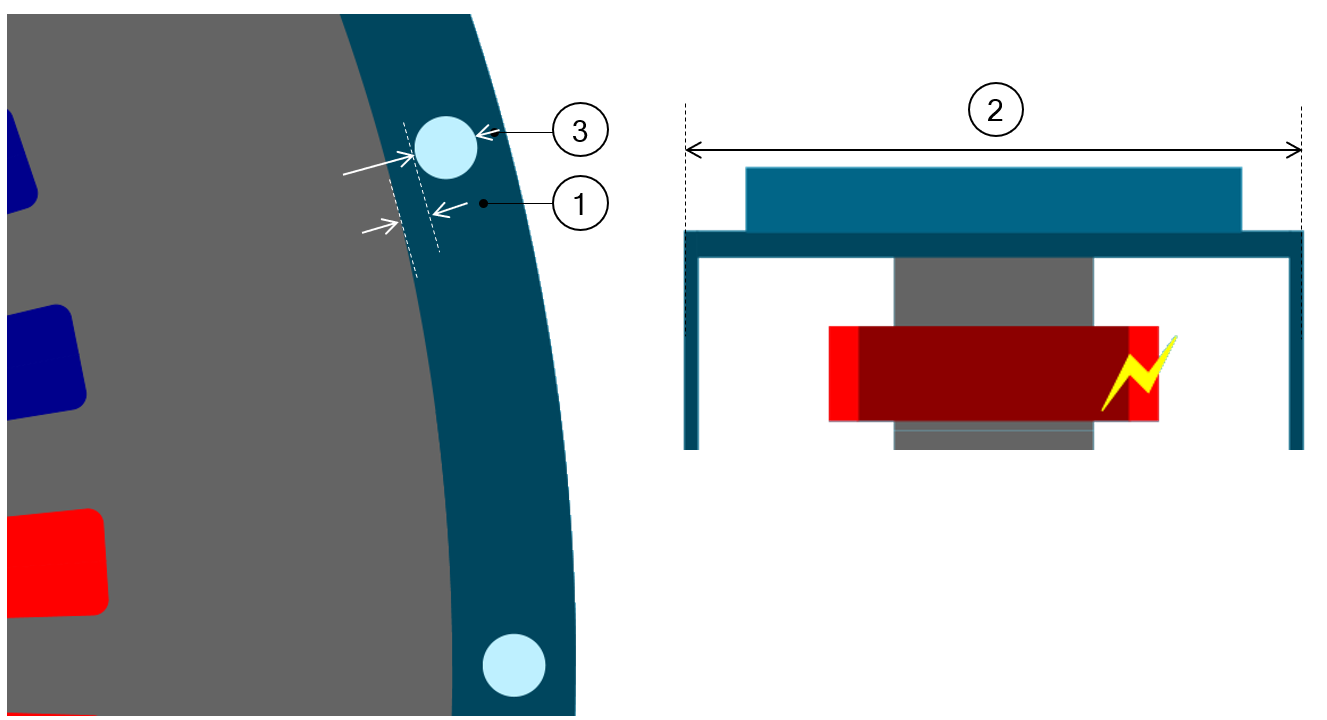
| Zig-Zag shape cooling circuit – With circular tubes - Inputs | |
| 1 | Yoke shift. |
| # | No. paths (Number of paths) |
| 2 | Path length in the axial direction |
| 3 | Section diameter |
–––––
Topology with rectangular section tubes - Inputs
 |
|
| Zig-Zag shape cooling circuit – With rectangular tubes - Inputs | |
| 1 | Yoke shift. |
| # | No. paths (Number of paths) |
| 2 | Path length in the axial direction |
| 3 | Section height |
| 4 | Section width |
Solenoid type cooling circuit
–––––
Area
 |
|
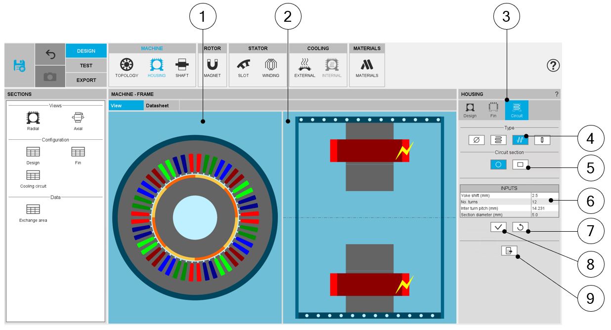
| Solenoid type cooling circuit - Design area | |
| 1 | Radial view of the motor, including the housing topology with cooling circuit topology and dimensions. |
| 2 | Axial view of the motor, including the housing topology with cooling circuit topology and dimensions. |
| 3 | The section Circuit (Cooling circuit) is selected to define the type and dimensions of the cooling circuit. |
| 4 | Selected button to define the topology of the cooling circuit. |
| 5 | Two sections can be considered: Circular (default one) and rectangular. |
| 6 | User input parameters to define the cooling circuit characteristics. For more information see below. |
| 7 | Button to restore default input values. |
| 8 | Button to apply inputs. Pressing the enter key twice applies inputs too. |
| 9 | Icon to export frame data into *.txt or *.xls files. |
–––––
Topology with circular section tubes - Inputs
 |
|
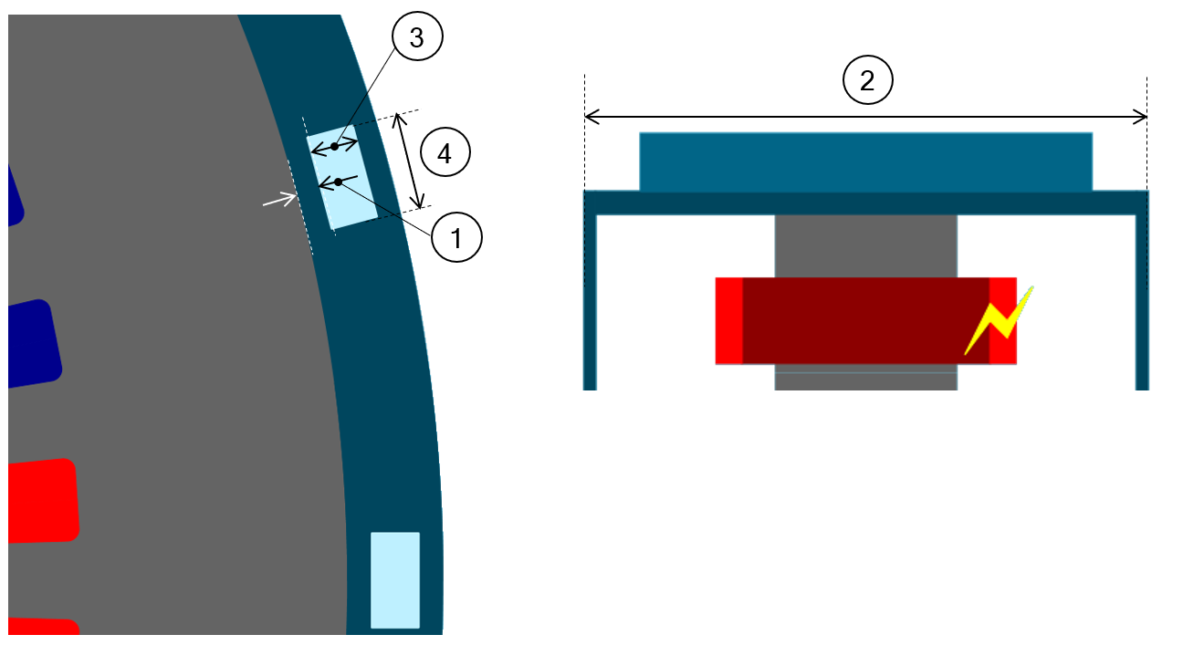
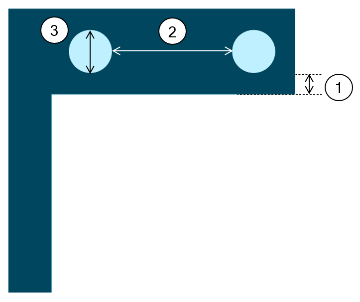
| Solenoid shape cooling circuit – With circular tubes - Inputs | |
| 1 | Yoke shift. |
| # | No. turns (Number of turns) |
| 2 | Inter turn pitch |
| 3 | Section diameter |
–––––
Topology with rectangular section tubes - Inputs
 |
|
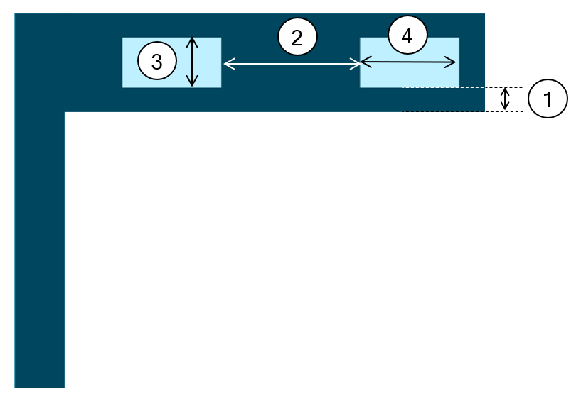
| Solenoid shape cooling circuit – With rectangular tubes - Inputs | |
| 1 | Yoke shift. |
| # | No. turns (Number of turns) |
| 2 | Inter turn pitch |
| 3 | Section height |
| 4 | Section width |
User type cooling circuit
–––––
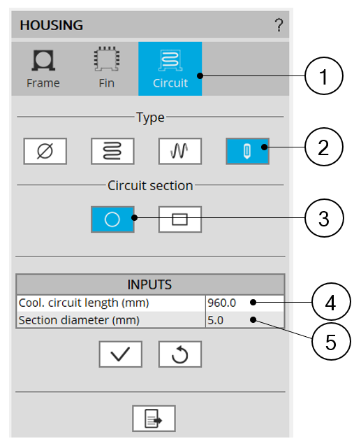
Topology with circular section tubes - Inputs
 |
|
| User shape cooling circuit – With circular tubes - Inputs | |
| 1 | The section Circuit (Cooling circuit) is selected to define the type and dimensions of the cooling circuit. |
| 2 | Selected button to define the topology of the cooling circuit. |
| 3 | Two sections can be considered: Circular (default one) and rectangular. |
| 4 | Cooling circuit length. |
| 5 | Section diameter of cooling circuit tubes. |
–––––
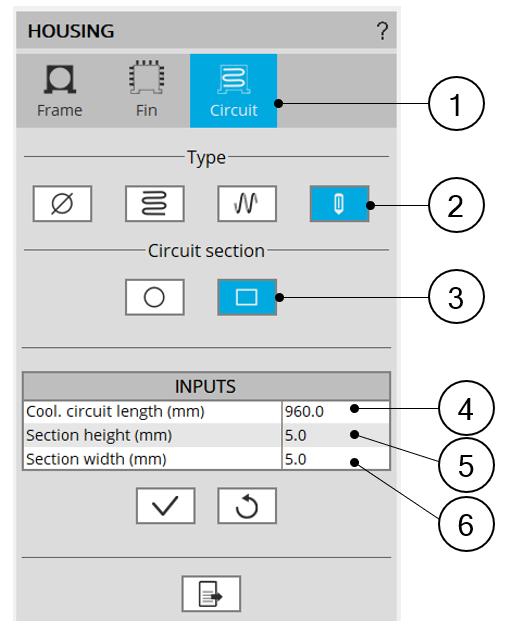
Topology with rectangular section tubes - Inputs
 |
|
| User shape cooling circuit – With rectangular tubes - Inputs | |
| 1 | The section Circuit (Cooling circuit) is selected to define the type and dimensions of the cooling circuit. |
| 2 | Selected button to define the topology of the cooling circuit. |
| 3 | Two sections can be considered: Circular (default one) and rectangular. |
| 4 | Cooling circuit length. |
| 5 | Section height of cooling circuit tube. |
| 6 | Section width of cooling circuit tube. |