Winding
Introduction
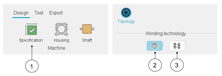
In Motor Factory, when the classical winding type or the hairpin winding type can be considered, this choice must be done in the Design area, in the environment “Specification”.
 |
|
|---|---|
| 1 | In Motor Factory – Design environment – Select the specification – Section “Topology” |
| 2 | Classical winding technology |
| 3 | Hairpin winding technology. Note: Hairpin
winding technology is available only for the 3-Phase inner rotor
machine. |
3-Phase and polyphase windings
The polyphase nature of the winding is not an option available in the machine specification. To design a polyphase machine, the user must select the appropriate machine type.
Structural data - Validity domain
The number of slots can be chosen over the range [3, 2400].
The number of poles can be chosen over the range [2, 400].
The number of phases can be chosen over the range [3,15]. Only odd values are considered.
- Range for number of slots [3, 90]
- Range for number of poles [2, 80]
- Range for number of phases [3,15]
Working beyond these bounds is possible, but accuracy of the results is the responsibility of the user.
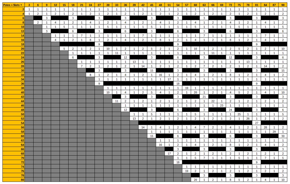
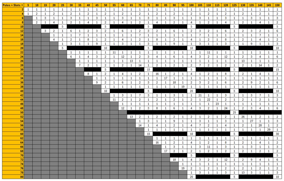
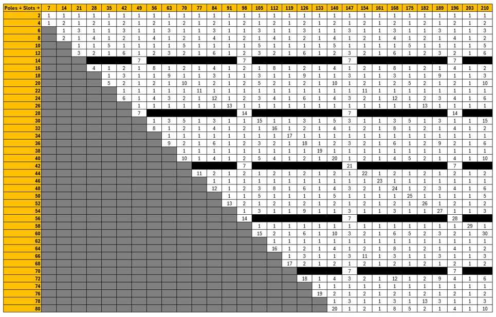
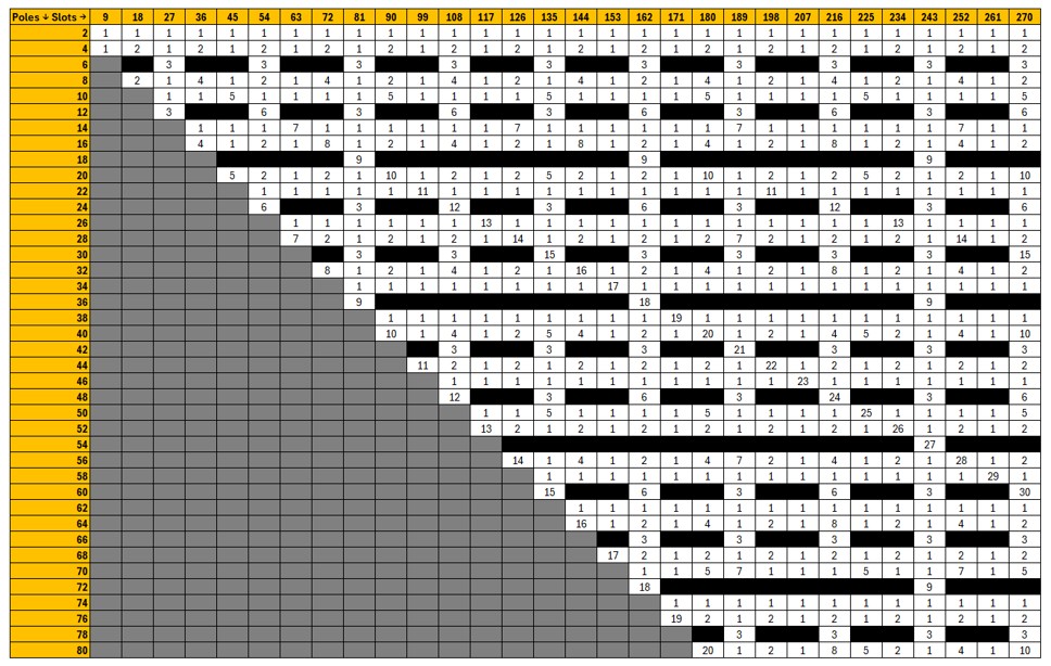
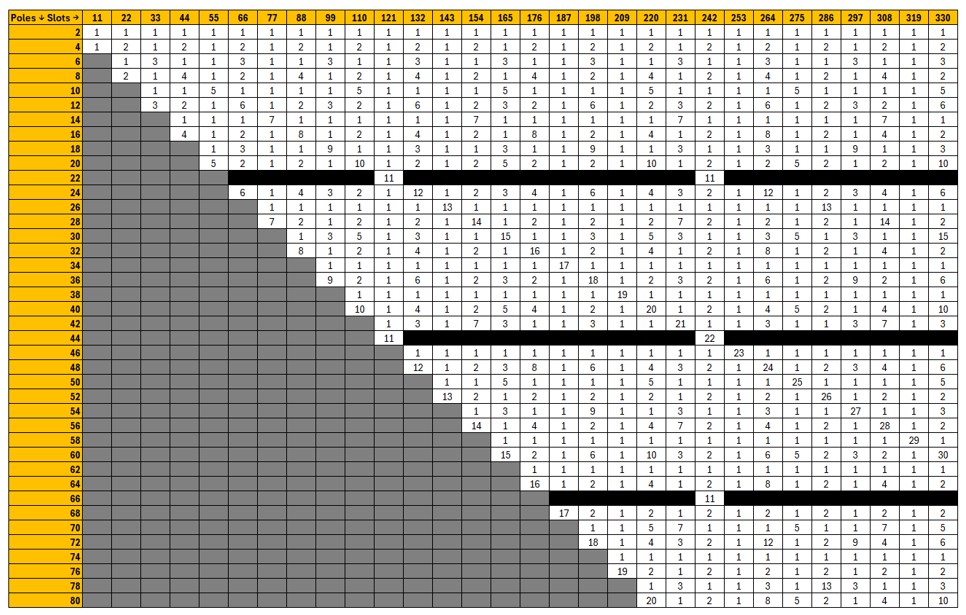
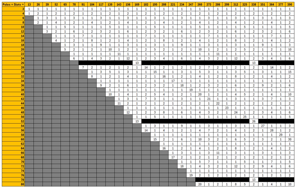
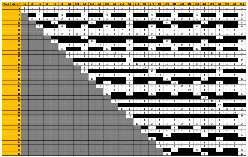
Three tables representing a selection of combinations of number of poles and number of slots for the most typical number of phases (three, five and seven) are presented below.
- For three-phase machines, the grey cells correspond to combinations with
a number of slots per pole per phase strictly lower than 0.25. These
cases are not allowed by our process.
Note: if the hairpin winding type is selected, only configurations with an integer number of slots per pole and per phase are allowed.
- The black cells correspond to forbidden combinations from a technological point of view.
- The numbers indicated in the other cells correspond to reduction coefficients to the resulting model in Altair Flux. For example, “1” means that the whole geometry is represented. “2” means that only half of the machine is represented, and “n” means that the 1/nth of the geometry is represented in the Flux® environment. That means it gives a general idea of the size of the model in Altair Flux software. Higher value gives the reduction coefficient and faster computation for a given motor.
Subsections
Introduction & Terminology
To read the full introduction dedicated to the classical and hairpin winding technologies, please refer to Introduction.
Classical & hairpin windings
For more details, please refer to Classical & hairping.