T - N
Positioning and objective
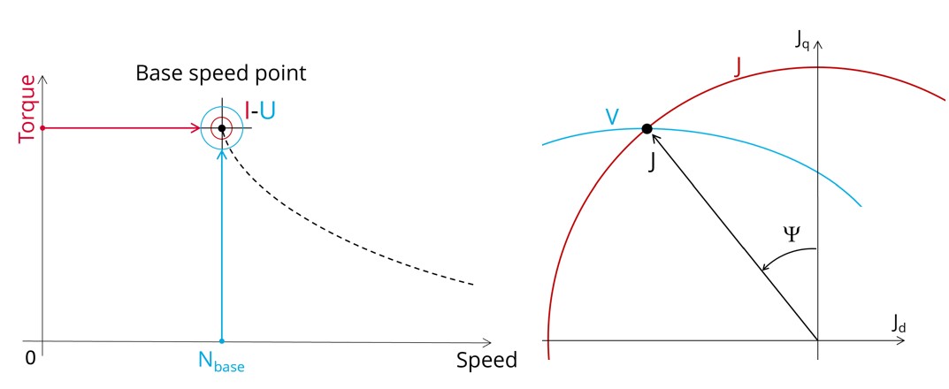
The aim of the test “Working point – Sine wave – Motor – T, N” is to characterize the behavior of the machine when operating at the working point which is targeted by the user. It corresponds to the base point at a targeted useful torque and speed.
The working point torque-speed is defined by considering the targeted input values T, N (useful torque, speed).
The results of this test give an overview of the electromagnetic analysis of the motor considering the machine topology.
The general data of the machine, like machine constants, power balance and magnet behavior are computed and displayed.
The following table helps to classify the test “Working point – Sine wave – Motor – T, N”.
| Family | Working point |
|---|---|
| Package | Sine wave |
| Convention | Motor |
| Test | T, N |
Inputs
For more details, please refer to Inputs.
Thermal
For more details, please refer to Thermal.
Electronics
For more details, please refer to Electronics.
Mechanics
For more details, please refer to Mechanics.