Efficiency map - Scalar(U-f)
Positioning and objective
The aim of the test “Performance mapping – Sine wave – Motor – Efficiency map scalar U-f” is to characterize the behavior of the machine in the "Torque-Speed" area.
Input parameters like, “the maximum Line-Line voltage, the rated power supply frequency, the maximum line current and the maximum speed” of the machine are considered.
One type of command mode is available: scalar command.
Input parameters define the torque-speed area in which the evaluation of the machine behavior is performed.
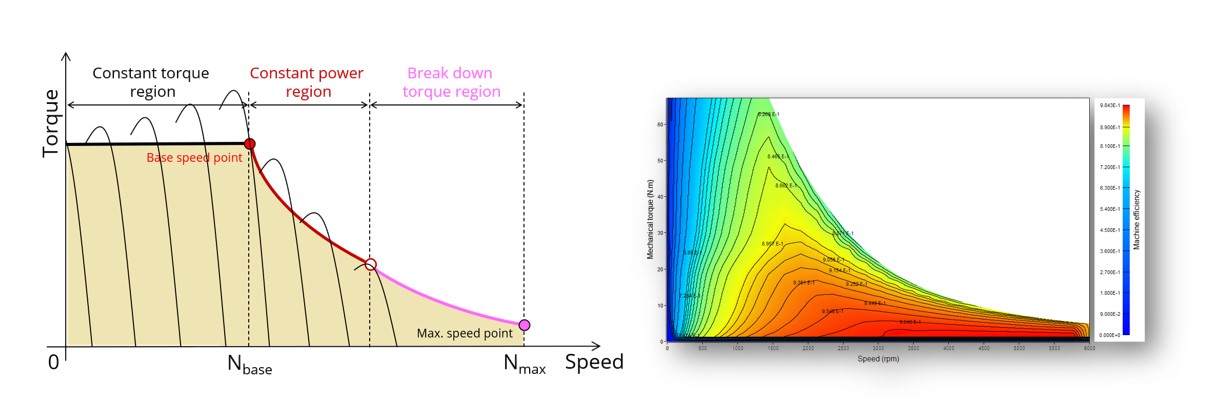
In the results, the performance of the machine at the base point (base speed point) and at the maximum speed (maximum speed point), set by the user are presented.
The following table helps in classifying the test “Performance mapping – Sine wave – Motor – Efficiency map scalar U-f”.
| Family | Performance mapping |
|---|---|
| Package | Sine wave |
| Convention | Motor |
| Test | Efficiency map scalar U-f |
Inputs
For more details, please refer to Inputs.
Thermal
For more details, please refer to Thermal.
Electronics
For more details, please refer to Electronics.
Mechanics
For more details, please refer to Mechanics.