Maps - Scalar
Positioning and objective
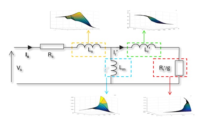
The aim of the test “Characterization – Model – Motor – Scalar” is to characterize the behavior of the machine in function of a set of Line-Line voltage (U) and a set of power supply frequency (f) (only motor operating mode available). Those computations are based on the identification and the solving of a non-linear model considering the cross saturation and the eddy current effects. All the main electromagnetic quantities are computed and displayed as curves in function of speed for a given power supply frequency and a set of Line-Line voltages.
The results of this test give an overview of the electromagnetic behavior of the machine considering its topology. For a set of Line-Line voltages (U) and a set of power supply frequencies (f), the general parameters of the machine like, mechanical torque, currents, power factor and power balance are computed and displayed as curves.
This gives the capability to make comparisons between the results obtained from the measurements and those with the Altair® FluxMotor.
The following table classifies the test “Characterization – Model – Motor – Scalar
| Family | Characterization |
|---|---|
| Package | Model |
| Convention | Motor |
| Test | Scalar |
Inputs
For more details, please refer to Inputs.
Thermal
For more details, please refer to Thermal.
Electronics
For more details, please refer to Electronics.
Mechanics
For more details, please refer to Mechanics.