Constant speed U-N
Positioning and objective
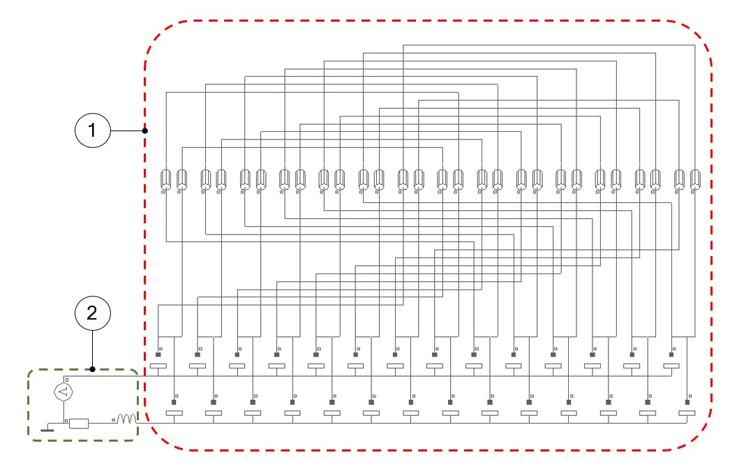
The aim of the test “Working point – Constant Speed – U-N” is to characterize the
behavior of the machine when operating at constant speed connected to an external
circuit composed of a DC voltage source and a parasitic impedance.
Note: The working point is mainly imposed by the external source
voltage and the machine rotation speed. Since these variables have a great
influence on the electrical and the mechanical sides, the working point may
correspond either to a motor or a to a generator behavior.
 |
|
|---|---|
| 1 | Circuit representation of the DC machine (including brushes – commutator segment contacts) |
| 2 | Circuit feeding the DC machine (including a DC voltage source and parasitic impedances) |
All the results are computed from a Finite Element Analysis (Flux) - Transient application. The results of this test give an overview of the electromagnetic behavior of the considered machine at a given working point.
The general data of the machine such as power balance, machine constant and torque ripple are computed and displayed.
The magnetic flux density is also computed in every region of the machine magnetic
circuit to evaluate the design.
Warning: A minimum
of two complete revolutions are considered for reaching a steady state behavior
of the machines. However, sometimes there is not enough time to ensure a good
convergence of our process; in this case the user is advised to compute a higher
number of revolutions (please, see the next sections for further
information).
Warning: Please note that
power motor convention will be maintained even if the machine behaves as a
generator for the selected working point.