 , with pole pair p, rotor flux
  and quadrature current
  . Scaled Integer (8.32)
Category: Toolbox > eDrives > Controllers
Inputs:
•freq_n: Normalized frequency reference. Scaled Integer (2.32)
•id_ref: Normalized d-axis current reference. Scaled Integer (2.32).
•iqref: Normalized q-axis current reference. Scaled Integer (2.32)
•i_a: Normalized measured alpha-axis current. Scaled Integer (2.32).
•i_b: Normalized measured beta-axis current. Scaled Integer (2.32)
•theta_n: Normalized theta (angle) measured. See Quadrature Encoder.
•udc_n: Normalized measured DC bus voltage. Scaled Integer (2.32)
•kpn: Normalized proportional gain Kp for speed loop. Scaled Integer (8.32)
•kin: Normalized integral gain Ki for speed loop. Scaled Integer (8.32)
•Speed_loop_on: Speed loop enable. (binary input)
•FOC_On: Field Oriented Control / Current Loop enable. (binary input)
•cntr_on: Controller enable. (binary input)
Outputs:
•mA_ref: Modulation index reference for phase A. Scaled Integer (8.32)
•mB_ref: Modulation index reference for phase B. Scaled Integer (8.32)
•mC_ref: Modulation index reference for phase C. Scaled Integer (8.32)
•speed_n: Normalized measured speed. Scaled Integer (8.32)
•isq_n: Normalized q-axis quadrature current used to
calculate the shaft torque  , with pole pair p, rotor flux
  and quadrature current
  . Scaled Integer (8.32)
Description: The Field Oriented Controller block generates modulation indices for three phase motor voltages. It uses both a speed loop and a current loop. It uses the rotor position and measured currents as feedback. It can be used with a Quadrature Encoder or Hall Sensor.
All inputs are divided by their respective full-scale values to get normalized values. For example, id_n = id_ref/C_fs, where id_ref is the user input and C_fs is the full-scale current.

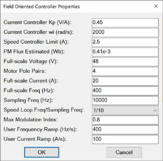
Current Controller Kp (V/A): Indicates the proportional gain for the current loop.
Current Controller wi (rad/s): Indicates the bandwidth of the current controller. Typically limited to 2000 rad/s.
Full-scale Current (A): Indicates the full-scale current value for normalization.
Full-scale Freq (Hz): Indicates the full-scale frequency value for normalization.
Full-scale Voltage (V): Indicates the full-scale voltage value for normalization.
Max Modulation Index: Indicates the maximum
modulation index value (absolute), which is the radius of a circle in the  plane.
Motor Pole Pairs: Indicates the number of magnetic pole pairs of the motor.
PM Flux Estimated (Wb): Indicates the estimated or calculated permanent magnetic flux of the motor used.
Sampling Freq (Hz): Used by the controller. This should be set to the same frequency as set in System > System Properties.
Speed Controller Limit (A): Indicates the current limit for q-axis reference current used by the speed controller.
Speed Loop Freq/Sampling Freq: This ratio helps set the frequency at which the speed loop operates.
User Current Ramp (A/s): Indicates the safety limit to avoid sudden jerks in the input current values .
User Frequency Ramp (Hz): Indicates the safety limit to avoid sudden jerks in the input frequency values.