The EEvision Plugins
.js” and can be loaded or unloaded by clicking the
corresponding checkbox in EEvision's settings dialog. The plugins listed in
the eev.conf
configuration file in the “plugins” field are
automatically loaded at startup time.
EEvision Basic Plugins
highlight.js
The highlight plugin makes it possible to highlight arbitrary schematic objects in different colors. It adds a color picker and a HL button to the plugin toolbar. The HL button adds highlighting using the currently active color of the color picker to (one or multiple) selected schematic objects. If a already highlighted object is selected, clicking the HL button removes highlighting from that element. If no schematic object is selected, clicking the HL button removes all highlighting from the schematic. The number of different highlight colors is limited to 20.
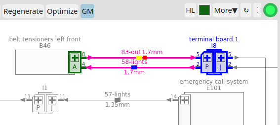
Additionally, the plugin requests for a graymode button (GM), which is added to the main toolbar. When graymode is activated, all items except the highlighted ones will appear in gray color.
full.js
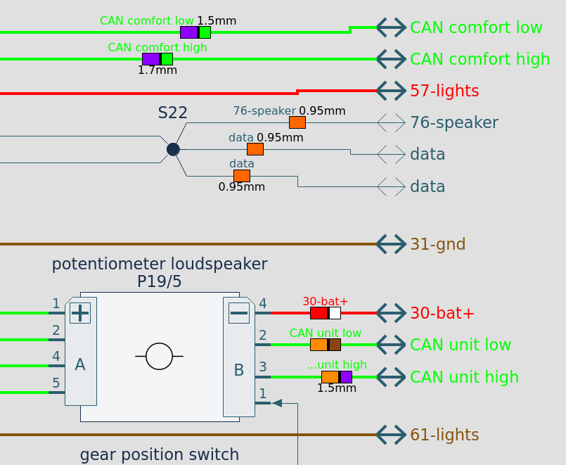
The full plugin shows the contents of the whole EDB as one schematic split into multiple pages. In addition to a Full button, the plugin adds a page selector to directly load a page of the schematic, as well as +/- buttons to increase or decrease the current page number.
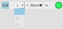
In full mode, so-called offpage connectors indicate that the wire continues on another page (doubleclicking the offpage connector directly jumps to that page).
It is still possible to select one or multiple objects and trigger a Load or Extract command. However, this will end full mode before the command is executed. Furthermore, the full mode disables the browser history, that is, clicking the forward/backward buttons will end full mode before the desired history state will be loaded.
validate.js
The validate plugin checks the loaded EDB database for semantic constraints that EEvision expects to be satisfied. More details can be found in the documentation of the plugin.
zoom.js
To simplify zooming the schematics on devices without a mouse wheel and without support for touch gestures (e.g., on laptops with only a touch pad) we provide the zoom.js plugin. It adds three buttons to the toolbar for zooming in, zooming out and fitting the current schematics into the EEvision window.
EEvision Pro Plugins
multicore.js
The multicore window shows the currently visible multicores in a tree structure. Each multicore entry is marked with a MC label. In addition to the multicore name it shows the multicore type (e.g., “sh/tw” for shielded and twisted). A click on the “+” button unfolds the current multicore showing submulticores or physical wires, which are labeled with a “W” label. If a multicore is unfolded, the “+”-button changes to a “–”-button, which collapses the branch again. Not yet visible wires are displayed in gray and a double-click loads and incrementally adds the wire to the schematic. A click on a wire entry of a visible wire selects and centers the wire in the schematic. A click on a multicore entry selects and centers all visible wires belonging to that multicore.
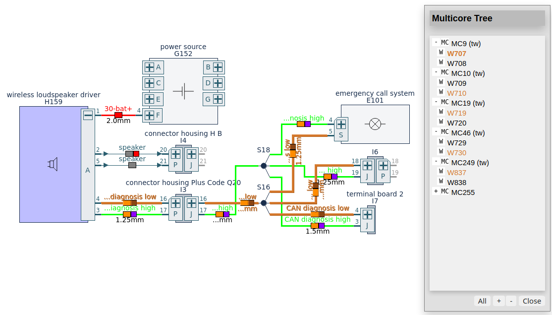
Selecting one or multiple wires in the schematic, highlights the corresponding entries in the multicore window as well. Selecting all wires of a multicore additionally highlights the multicore entry. The +/- buttons below the contents section explode/collapse the complete multicore tree at once. The All button additionally shows all non-visible multicores in the tree making it possible to load and explore all multicores defined in the EDB.
endcircuit.js
The endcircuit plugins allows to show the internal circuitry of an ECU component. The details how to use the endcircuit plugin are described in a separate manual.
modedit.js
The module editor plugin (modedit) adds the currently visible schematic as a new module to the EDB on the server. In the modedit dialog, the user can specify a module name and a module type. A click on the Add button adds a new module of the specified type and name to the EDB.
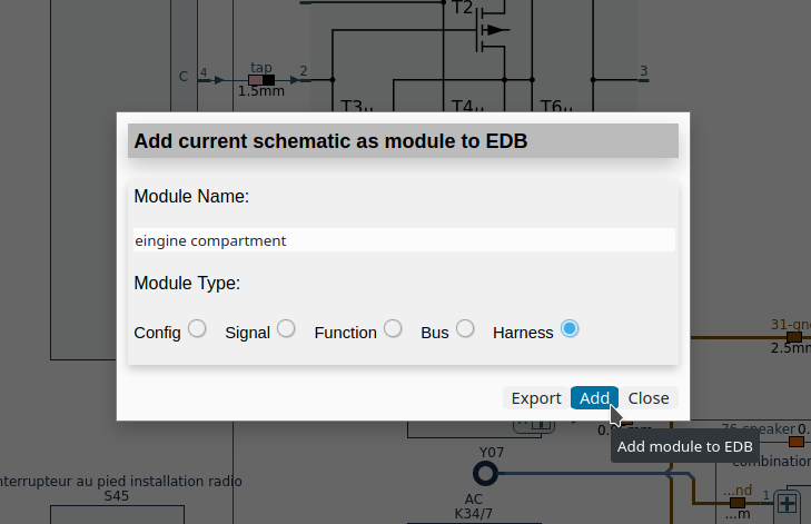
This procedure can be repeated as often as required. Finally, the user can
download the modified EDB by clicking the Export button in the modedit
dialog.
Important: Before the EDB is exported, the newly added modules are
only present in memory, that is, for example when EEvision is reloaded,
all this information will be lost. The Export of the EDB requires write
permissions in the EEvision data directory. Here it temporarily stores the
modified EDB.
modnav.js
The module navigator plugin (modnav) gives an overview of all modules in the EDB and lets the user load, add and highlight the modules. A selection box at the top of the dialog lists all available module classes. All modules in the EDB belonging to the currently selected class are listed in a table in the section below. The module name is displayed in black, if at least one member of the module is visible in the current schematic, and displayed in gray color otherwise. For each module, the user can choose a color and highlight all visible module members by activating the checkbox. Initially, 26 well distinguishable colors are distributed over the module entries. Likewise to the Live Search result window, the module can be loaded as a new schematic (L button) or added to the current schematic (+ button).
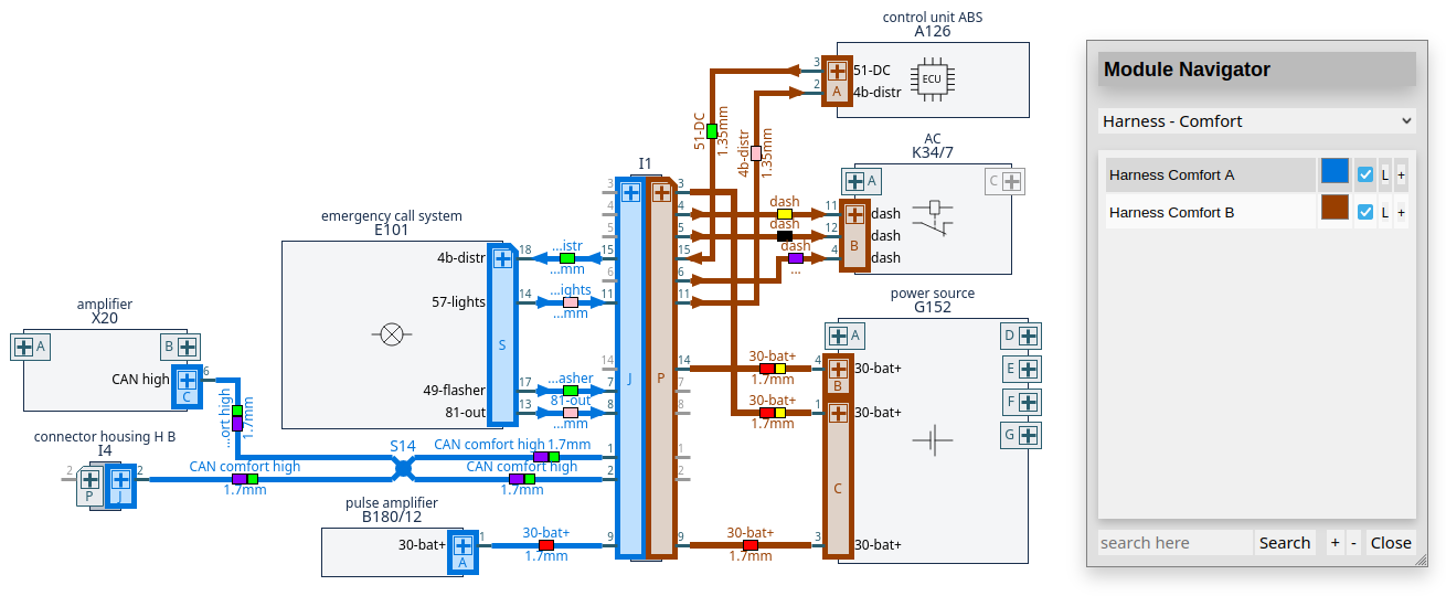
The +/- buttons below the table add/remove highlight color for all modules of the currently selected module class at once. If one schematic object belongs to multiple modules of the current class, it is highlighted in the color of the last activated module. When the module class is changed, all highlight color is removed from the schematic, however the selected colors of the individual modules are saved, that is, if the user switches back to a certain module class, the previously selected colors are restored. The number of different highlight colors is limited to 80. A search bar allows to find modules in the currently selected module class. The internal " subtype" attribute at modules is used to add a further subtype category to the module class. If the module class is undefined, the " subtype" attribute defines a new module class.
EEvision Enterprise Plugins
docgen.js
The automatic document generator (docgen) is a plugin to automatically generate a PDF document, which contains a selected set of schematics enriched by additional information like a technical frame or a "bill of material" (BOM).
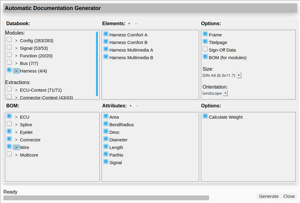
The docgen dialog consists of six sections, which allow for a precise selection of the schematics to generate and further configuration of the PDF document layout. The Databook section lists the predefined EEvision module classes (Modules) and extraction modes (Extractions). Activating the checkbox includes the corresponding set of schematics to the PDF. Clicking the > button lets the user further select or deselect each element of the class in the Elements section of the GUI (the +/- buttons right to the Elements header select/deselect all elements at once). For each selected element, the docgen plugin generates one page containing the schematic for either the complete module or the extraction of the ECU. In case of the Connector-Context, the plugin generates one page for each connector of the selected ECU.
The Options section lets the user add additional information and change the page layout:
- Frame: Adds a technical frame to each schematic page containing additional information like page size, date, EDB name, module name, etc.
- Titlepage: Adds a titlepage before each new databook class.
- Sign-Off Data: Add data of the sign-off plugin (not available yet, work in progress)
- BOM: Add a bill of material for each module on an extra page (see below).
- Size: Choose page size between DIN A4 and ANSI B.
- Orientation: Choose page orientation (landscape or portrait).
If the BOM checkbox is enabled, the three lower sections become active to configure the BOM tables. In the BOM section, the user can specify which types of objects are added to the tables. A click on the > button lists all available attributes for the corresponding type in the Attributes section. The selected attributes will be added to each table entry in the PDF. Likewise to the Elements section, the +/- buttons select resp. deselect all listed items. Finally, the user can activate the weight calculation in the Options section, which sums up the mass of all objects for one module and adds the result to the bottom of the BOM table.
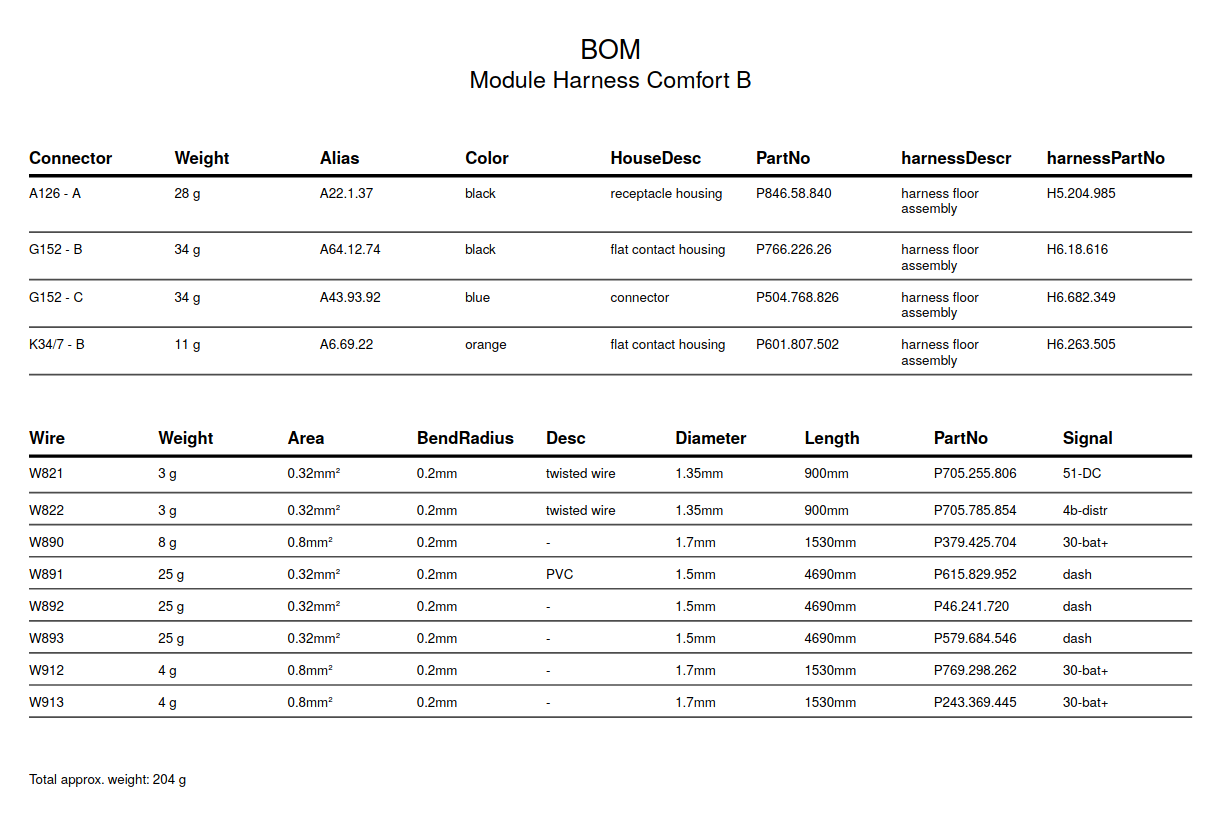
The weight calculation algorithm only considers objects which have a
“␣weight” attribute set. The value is a
unit-less number, the default unit is gram. For components (ECU, splices,
and eyelets) the number denotes the weight in grams. However, for wires
there are two options: If there is an additional wire attribute
“␣length”, the value of
“␣weight” is interpreted as grams per meter
resp. kilograms per kilometer and the value of
“␣length” as millimeter. The product of both
values divided by 1000 yields the weight of the wire. In case there is no
“␣length” attribute, the
“␣weight” denotes the absolute mass of the wire
in grams (likewise to components). Objects lacking the
“␣weight” attribute are silently ignored for
the mass calculation.